Настройка Firewall в Mikrotik
RouterOS — сетевая ОС, изначально предназначенная для устройств RouterBoard латвийской компании Mikrotik, но в дальнейшем перекочевавшая на x86 и в облака (версия Cloud Hosted Router). В этой статье поговорим о том, как грамотно настроить межсетевой экран в этой ОС. Безопасность периметра локальной сети — одна из приоритетных задач любого системного администратора и в компании Mikrotik […]

RouterOS — сетевая ОС, изначально предназначенная для устройств RouterBoard латвийской компании Mikrotik, но в дальнейшем перекочевавшая на x86 и в облака (версия Cloud Hosted Router). В этой статье поговорим о том, как грамотно настроить межсетевой экран в этой ОС.
Безопасность периметра локальной сети — одна из приоритетных задач любого системного администратора и в компании Mikrotik это прекрасно понимают. Так что как только вы включили устройство на RouterBoard с настройками по умолчанию — там уже будет некоторое количество преднастроенных правил. В случае Mikrotik CHR — по умолчанию правил не будет, но Mikrotik настоятельно рекомендует их настроить.
Сразу оговоримся, что в рамках этой статьи мы будет пользоваться исключительно интерфейсом командной строки (CLI) и облачной версией RouterOS CHR. Логика настройки точно такая же, как и при использовании WinBox или WebFig, но предпочтительнее изначально пользоваться CLI.
Немного теории: настройка firewall
Одним из базовых понятий настройки файервола Mikrotik является цепочка (chain). По умолчанию их 3, но есть возможность и создания собственных цепочек:
- Цепочка INPUT — входящий трафик, приходящий на маршрутизатор.
- Цепочка OUTPUT — исходящий трафик, создаваемый маршрутизатором.
- Цепочка FORWARD — трафик, проходящий сквозь через маршрутизатор.
Если к нам должен прийти какой-либо трафик извне, например, из интернета, то мы его будем обрабатывать цепочкой INPUT. Чтобы обработать правилами трафик, уходящий наружу (например, в тот же интернет), задействуем цепочку OUTPUT. Если же наш маршрутизатор не находится на границе сети, а служит промежуточным узлом между сетями, то тогда для обработки трафика применяем цепочку FORWARD.
Причем тут странное название «цепочка»? Все элементарно. Все создаваемые правила обработки действуют не вместе, а строго по очереди одно за другим. Точно также, как формируется цепь — одно звено следует за другим. Именно поэтому списки правил стали именовать «цепочками».
Теперь коснемся статусов соединения. Каждое соединение условно можно разделить на 4 категории:
- New — исходя из названия ясно, что это новое соединение, а не одно из существующих.
- Established — соединение установлено, по нему можно передавать пакеты данных.
- Related — соединение, которое относится уже к какому-либо из существующих, но используемое в иных целях. Пока не будем заострять на этом внимание, чтобы не усложнять.
- Invalid — некорректное соединение, то есть маршрутизатор понятия не имеет, что это за соединение и как его обрабатывать.
И сразу к практике: фильтрация
Открываем консольный интерфейс и посмотрим на существующие правила:
[admin@MikroTik] > ip firewall filter print Flags: X - disabled, I - invalid, D - dynamicПока что правил нет, отображается только «легенда» про флаги. Переходим в раздел настройки фильтров:
[admin@MikroTik] > ip firewall filter [admin@MikroTik] /ip firewall filter>Полезный чит-код: узнать все варианты команд в любом разделе можно, нажав клавишу со знаком вопроса «?«
Теперь создадим несколько правил и расскажем для чего они нужны:
add action=accept chain=input comment="default configuration" connection-state=established,relatedЭту команду можно читать прямо дословно. Разберем прямо по пунктам:
- add action=accept — принимать пакеты.
- chain=input — правило будет работать в цепочке входящего трафика.
- comment=»default configuration» — это просто комментарий-напоминалка, в нашем случае указываем, что это конфигурация по умолчанию, но можно вообще этот параметр не указывать.
- connection-state=established,related — указываем какие статусы соединения будем принимать.
Таким образом эта длинная команда всего лишь превращается во вполне логичную фразу «Принимать извне все пакеты со статусом соединения Established и Related». Это правило позволяет четко указать маршрутизатору что если из внешней сети прилетают соединения с указанными статусами, то их следует принять.
Теперь переходим к следующему правилу, рекомендуемому Mikrotik:
add action=accept chain=input src-address-list=allowed_to_routerТут мы заострим внимание только на параметре src-address-list=allowed_to_router. При обработке трафика мы можем формировать различные списки IP-адресов. Каждый список будет иметь имя. Так что дословный «перевод» этого правила всего лишь «Принять пакеты, если IP-адрес с которого обращаются, есть в списке allowed_to_router. Нам это правило пригодится для дальнейшего формирования списка разрешенных IP-адресов.
Еще небольшое пояснение. Из-за того, что правила в цепочке обрабатываются одно за другим, то вначале следует прописывать разрешающие правила, а только после этого запрещающие.
Теперь следующее правило, оно достаточно спорное. Мы разрешим маршрутизатору отвечать на команду ping, приходящую извне. С одной стороны — это потенциально раскрывает то, что на нашем IP-адресе есть действующее устройство, а с другой это часто требуется для организации мониторинга. У нас в Selectel, к примеру есть услуга «Мониторинг состояния сервисов», которая позволяет отслеживать доступность любого хоста из разных стран мира. Если вам нужно, отключить ping, то в action надо прописать не accept, а drop.
add action=accept chain=input protocol=icmpТут все просто — эта команда разрешает принимать извне и обрабатывать ICMP-пакеты. И завершающая команда:
add action=drop chain=inputЭтим в финале цепочки INPUT мы будем отбрасывать (дропать) все оставшиеся пакеты, не подпадающие под правила выше. Посмотрим как у нас сформировались правила:
[admin@MikroTik] /ip firewall filter> print Flags: X - disabled, I - invalid, D - dynamic 0 ;;; default configuration chain=input action=accept connection-state=established,related 1 chain=input action=accept src-address-list=allowed_to_router 2 chain=input action=accept protocol=icmp 3 chain=input action=dropРассмотрим как же это работает. Представим, что мы пингуем маршрутизатор извне. Это выглядит примерно так:
- Прилетел снаружи ICMP-пакет. Машрутизатор смотрит в правило номер 0 — есть ли уже установившееся соединение. Если нас пингуют впервые, то статус соединение будет New, а не Established или Related. Так что правило не срабатывает.
- Смотрим дальше — есть ли IP-адрес с которого пришел пакет в списке allowed_to_router. Поскольку мы этот список еще не формировали, то его еще не существует и, следовательно, правило также не срабатывает.
- Наконец доходим до правила 2, которое однозначно говорит маршрутизатору, что следует принять (Accept) и обработать по протоколу ICMP данный пакет. Маршрутизатор отвечает на ICMP-пакет соответствующим эхо-ответом. До четвертого правила пакет уже не добирается, т.к. процедура обработки фактически завершена.
Рассмотрим еще один случай. На этот раз к нам на маршрутизатор извне прилетел некий неизвестный UDP-пакет с данными. Как будет действовать маршрутизатор:
- Смотрим правило 0. Существующего Established или Related соединения у нас нет, поэтому правило не срабатывает.
- Правило 1 — смотрим в список разрешенных адресов allowed_to_router, но там пусто. Еще одно правило не сработало.
- Дошли до правила 2 — является ли пришедший пакет ICMP-пакетом. Нет, не является, так что правило не срабатывает.
- И вот мы дошли до конца цепочки INPUT, где нас поджидает «правило-вышибала”. Поскольку у правила chain=input action=drop нет условий для срабатывания, то оно по умолчанию срабатывает всегда и наш неизвестный UDP-пакет дропается и перестает существовать.
Надеемся, что столь подробный разбор логики немного прояснил как именно работает файервол в Mikrotik RouterOS, поэтому приступим к дальнейшей настройке. Сформируем список разрешенных адресов. Для этого вернемся в главное меню, нажав символ / и подтвердив нажатием клавиши Enter. Теперь перейдем в раздел консольного интерфейса Mikrotik – ip firewall и посмотрим какие адресные списки у нас существуют:
[admin@MikroTik] > ip firewall address-list [admin@MikroTik] /ip firewall address-list> print Flags: X - disabled, D - dynamic # LIST ADDRESS CREATION-TIME TIMEOUTКак видим, список пока пустой. Добавим туда адреса из стандартной локальной подсети 192.168.88.0/24 за исключением 192.168.88.1 (адрес маршрутизатора). Эта подсеть обычно используется по умолчанию на устройствах Mikrotik и именно ее чаще всего используют для раздачи адресов в локальной сети. Выполним добавление:
add address=192.168.88.2-192.168.88.254 list=allowed_to_routerКоманда максимально проста для понимания мы говорим, что нам нужно добавить адреса 192.168.88.2-192.168.88.254 в список с именем allowed_to_router. Подразумевается то, что если списка с таким именем не существует, то при выполнении команды он будет создан. Проверим:
[admin@MikroTik] /ip firewall address-list> print Flags: X - disabled, D - dynamic # LIST ADDRESS CREATION-TIME TIMEOUT 0 allowed_to_router 192.168.88.2-192.168.88.254 feb/05/2021 13:01:55Теперь, когда файервол в цепочке INPUT дойдет до правила номер 1, то в случае поступления данных с IP-адресом отправителя из диапазона 192.168.88.2-192.168.88.254 — правило сработает и маршрутизатор будет знать, что данные следует принять. Этим мы будем пользоваться для обращений к маршрутизатору из локальной сети.
Разделяем и властвуем
Списки адресов — крайне полезная штука при настройке файервола. Тут важно следовать стандартам, разработанным такой крутой организацией, как IETF (Internet Engineering Task Force) — Инженерный совет Интернета. Это международное сообщество с конца 80-х годов занимается развитием протоколов и архитектуры интернета.
Результаты работы IEFT публикуются в виде RFC (Request for Comments) — информационных документов, содержащих в себе детальное описание спецификаций и стандартов. Этих документов уже создано несколько тысяч, все они представлены на английском языке. Один из них поможет нам корректно сформировать списки адресов, а именно RFC6890.
Наша задача при настройке файервола четко разделить адреса, относящиеся к локальному сегменту и адреса глобальной сети интернет. Именно их мы возьмем из RFC и пропишем в нашем маршрутизаторе списком с названием not_in_internet. В дальнейшем это поможет нам сформировать правила в которых будут абстракции «это адрес из интернета» и «это адрес не из интернета».
Поочередно выполняем команды, создавая и дополняя список not_in_internet, помимо всего прочего указывая в комментарии номер RFC, которым мы руководствовались:
add address=0.0.0.0/8 comment=RFC6890 list=not_in_internetadd address=172.16.0.0/12 comment=RFC6890 list=not_in_internetadd address=192.168.0.0/16 comment=RFC6890 list=not_in_internetadd address=10.0.0.0/8 comment=RFC6890 list=not_in_internetadd address=169.254.0.0/16 comment=RFC6890 list=not_in_internetadd address=127.0.0.0/8 comment=RFC6890 list=not_in_internetadd address=198.18.0.0/15 comment=RFC6890 list=not_in_internetadd address=192.0.0.0/24 comment=RFC6890 list=not_in_internetadd address=192.0.2.0/24 comment=RFC6890 list=not_in_internetadd address=198.51.100.0/24 comment=RFC6890 list=not_in_internetadd address=203.0.113.0/24 comment=RFC6890 list=not_in_internetadd address=100.64.0.0/10 comment=RFC6890 list=not_in_internetadd address=240.0.0.0/4 comment=RFC6890 list=not_in_internetЕсть еще две важные подсети, которые тоже стоит добавить в этот список. Первая подсеть — это 224.0.0.0/4. Эта подсеть зарезервирована для технологии многоадресного вещания (мультикаст) и это зафиксировано в соответствующем RFC2780. Вторая подсеть специфична для переходного механизма 6to4, позволяющего передавать IPv6 трафик через IPv4 сети. Этот механизм реализован в подсети 192.88.99.0/24, что также зафиксировано в отдельном RFC3068.
add address=224.0.0.0/4 comment=Multicast_RFC2780 list=not_in_internetadd address=192.88.99.0/24 comment="6to4_RFC 3068" list=not_in_internetТеперь, когда мы все сделали «по фен-шую», у нас есть список всех адресов, которые будут опознаваться как локальные, т.е. пришедшие не из интернета. Проверим:
[admin@MikroTik] /ip firewall address-list> print Flags: X - disabled, D - dynamic # LIST ADDRESS CREATION-TIME TIMEOUT 0 allowed_to_router 192.168.88.2-192.168.88.254 feb/05/2021 13:01:55 1 ;;; RFC6890 not_in_internet 0.0.0.0/8 feb/05/2021 13:43:03 2 ;;; RFC6890 not_in_internet 172.16.0.0/12 feb/05/2021 13:43:03 3 ;;; RFC6890 not_in_internet 192.168.0.0/16 feb/05/2021 13:43:03 4 ;;; RFC6890 not_in_internet 10.0.0.0/8 feb/05/2021 13:43:03 5 ;;; RFC6890 not_in_internet 169.254.0.0/16 feb/05/2021 13:43:03 6 ;;; RFC6890 not_in_internet 127.0.0.0/8 feb/05/2021 13:43:03 7 ;;; RFC6890 not_in_internet 198.18.0.0/15 feb/05/2021 13:43:03 8 ;;; RFC6890 not_in_internet 192.0.0.0/24 feb/05/2021 13:43:03 9 ;;; RFC6890 not_in_internet 192.0.2.0/24 feb/05/2021 13:43:03 10 ;;; RFC6890 not_in_internet 198.51.100.0/24 feb/05/2021 13:43:03 11 ;;; RFC6890 not_in_internet 203.0.113.0/24 feb/05/2021 13:43:03 12 ;;; RFC6890 not_in_internet 100.64.0.0/10 feb/05/2021 13:43:03 13 ;;; RFC6890 not_in_internet 240.0.0.0/4 feb/05/2021 13:43:03 14 ;;; Multicast_RFC2780 not_in_internet 224.0.0.0/4 feb/05/2021 13:43:12 15 ;;; 6to4_RFC3068 not_in_internet 192.88.99.0/24 feb/05/2021 13:43:12 Теперь, используя эти листы, создадим еще правила уже в цепочке FORWARD, которые защитят устройства в локальной сети от различных посягательств. Возвращаемся в раздел с правилами:
/ip firewall filterПервым правилом мы сделаем так, чтобы наш файервол не срабатывал, когда имеет дело с уже установленными соединениями, это лишь тратит ресурсы маршрутизатора и никоим образом не помогает в обеспечении безопасности:
add action=fasttrack-connection chain=forward comment=FastTrack connection-state=established,relatedОбрабатываем установленные соединения в цепочке Forward:
add action=accept chain=forward comment="Established, Related" connection-state=established,relatedОтбрасываем «битые» соединения:
add action=drop chain=forward comment="Drop invalid" connection-state=invalid log=yes log-prefix=invalidОтбрасываем пакеты, исходящие из локальной сети к частным IP-адресам и фиксируем срабатывание правила в логах:
add action=drop chain=forward comment="Drop tries to reach not public addresses from LAN" dst-address-list=not_in_internet in-interface=bridge1 log=yes log-prefix=!public_from_LAN out-interface=!bridge1Отбрасываем входящие пакеты, которые не подходят для NAT и фиксируем срабатывание:
add action=drop chain=forward comment="Drop incoming packets that are not NATted" connection-nat-state=!dstnat connection-state=new in-interface=ether1 log=yes log-prefix=!NATОтбрасывать пакеты из сети интернет, пришедшие не с публичных IP-адресов и заносить информацию в лог:
add action=drop chain=forward comment="Drop incoming from internet which is not public IP" in-interface=ether1 log=yes log-prefix=!public src-address-list=not_in_internetОтбрасывать пакеты из локальной сети, не имеющие IP-адресов этой локальной сети, и также отправляем сообщение в лог:
add action=drop chain=forward comment="Drop packets from LAN that do not have LAN IP" in-interface=bridge1 log=yes log-prefix=LAN_!LAN src-address=!192.168.88.0/24Защита от атак перебором
Брутфорс-атаки давно стали повседневностью. Десятки тысяч ботов регулярно сканируют весь интернет в поисках открытых портов SSH и затем начинают весьма активно «стучаться» на внешний интерфейс и перебирать пароли в попытке захватить контроль над подключенным устройством. У тех, кто контролирует эти сети есть весьма обширные словари паролей, использующие как дефолтные реквизиты доступа большинства устройств.
Но даже если вы задали сложный пароль — это еще не гарантирует безопасности. Длительная атака перебором способна сломать этот барьер защиты, поэтому проще всего пресекать попытки злоумышленников сразу, как только замечен процесс перебора. Настройка правил firewall у устройств Mikrotik достаточно тривиальна:
Вначале создадим правило firewall по которому все входящие соединения с IP-адресов, находящихся в списке ssh_blacklist будут сбрасываться:
add chain=input protocol=tcp dst-port=22 src-address-list=ssh_blacklist action=drop comment="Drop SSH brutforce" disabled=noТеперь сформируем сам список ssh_blacklist. Любой имеет право на ошибку, поэтому если легитимный пользователь три раза ошибся во вводе пароля — это нормально. Так что позволим пользователю сделать 3 ошибки с интервалом в 1 минуту. Большее количество будет свидетельствовать о переборе паролей и IP-адрес атакующего будет попадать в черный список и включается блокировка на 10 дней.
Так что нам потребуется создать еще три списка IP-адресов. Первый назовем ssh_stage1. Как только создается новое соединение на порт SSH мы вносим IP-адрес источника в список. При этом задаем удаление через 1 минуту. Это гарантирует нам то, что если соединение прошло успешно — IP-адрес будет удален из списка.
add chain=input protocol=tcp dst-port=22 connection-state=new action=add-src-to-address-list address-list=ssh_stage1 address-list-timeout=1m comment="Stage1" disabled=noЕсли даже пользователь ошибся, то ничего страшного, однако если он попробует в течение этой минуты еще раз подключиться, то его адрес мы закидываем во второй список ssh_stage2 из первого списка ssh_stage1.
add chain=input protocol=tcp dst-port=22 connection-state=new src-address-list=ssh_stage1 action=add-src-to-address-list address-list=ssh_stage2 address-list-timeout=1m comment="Stage2" disabled=noЕсли пользователь ошибется второй раз, то закидываем IP-адрес источника из списка ssh_stage2 в список ssh_stage3.
add chain=input protocol=tcp dst-port=22 connection-state=new src-address-list=ssh_stage2 action=add-src-to-address-list address-list=ssh_stage3 address-list-timeout=1m comment="" disabled=noТретья ошибочная попытка приводит к копированию IP из списка ssh_stage3 в список ssh_blacklist и все входящие соединения с этого IP будут заблокированы сроком на 10 дней.
add chain=input protocol=tcp dst-port=22 connection-state=new src-address-list=ssh_stage3 action=add-src-to-address-list address-list=ssh_blacklist address-list-timeout=10d comment="" disabled=noДля разблокировки адреса будет достаточно его удалить из черного списка.
NAT: базовая настройка и проброс портов
Технология трансляции сетевых адресов (NAT — Network Address Translation) используется во многих случаях. Чаще всего с ней можно встретиться при организации широкополосного доступа к сети интернет. Смысл технологии в том, чтобы дать возможность выходить в сеть множеству устройств, используя всего лишь один внешний IP-адрес.
Все устройства в этом случае будут иметь локальные IP-адреса, например, 192.168.XXX.XXX. Когда устройство запрашивает какой-либо внешний ресурс, то маршрутизатор точно знает от какого адреса в локальной сети пришел запрос и соответственно знает куда направлять обратный поток данных. Но если из внешней сети придет какой-либо запрос, то маршрутизатор его отбросит, поскольку не знает какому устройству в локальной сети его направить.
Решением проблемы является так называемый проброс портов (Port Forwarding). Создавая правило проброса портов мы даем маршрутизатору указания какому устройству перенаправить запрос извне. На логическом уровне подобный запрос может выглядеть как «Если на порт XXX придет TCP-запрос, то перенаправь его на локальный адрес 192.168.XXX.XXX на порт YYY». Давайте посмотрим 2 способа как нам настроить NAT на Mikrotik.
Способ 1. Когда выходной IP-адрес может меняться
Изначально Mikrotik ничего о нашем намерении использовать NAT не знает. Для начала укажем, что хотим все пакеты, пришедшие из локальной сети выводились во внешнюю сеть через общий IP-адрес:
ip firewall nat add chain=srcnat out-interface=ether1 action=masqueradeгде ether1 — интерфейс, смотрящий в интернет. Также можно задать не один выходной интерфейс, а сразу несколько, заранее сформировав список out-interface-list.
Этот способ наиболее простой и удобный для пользователей с динамическим IP-адресом.
Способ 2. Когда выходной IP-адрес статический и не меняется
Теперь еще один вариант организации NAT. Рассмотрим пример:
ip firewall nat add chain=srcnat out-interface=ether1 action=src-nat to-addresses=XXX.XXX.XXX.XXXгде XXX.XXX.XXX.XXX — статический IP-адрес, а ether1 — выходной интерфейс.
Теперь переходим к пробросу портов. Для примера предположим, что у нас в локальной сети 192.168.88.0/24 есть небольшой сервер по адресу 192.168.88.10 с поднятым SSH. Нам нужно подключаться к серверу удаленно, используя номер порта 1122. Для этого выполним проброс портов, созданием правила:
ip firewall nat add chain=dstnat in-interface=ether1 protocol=tcp dst-port=1122 action=dst-nat to-addresses=192.168.88.10 to-ports=22Почему мы взяли такой странный номер порта 1122? Все просто — чтобы затруднить злоумышленникам нахождение номера порта и последующего перебора реквизитов. Таким образом, мы создали правило, однозначно позволяющее маршрутизатору понять, что все TCP-пакеты, пришедшие на порт 1122 следует переадресовывать на локальный адрес 192.168.88.10 на порт 22.
Вместо заключения
Мы рассмотрели основные команды для выстраивания базовой защиты для устройств на базе RouterBoard, а также облачной версии Mikrotik CHR и взглянули на то, как можно парой команд настроить NAT. Разумеется, для каждого неиспользуемого сервиса можно закрыть доступ извне, исходя из используемых портов, протоколов и типа трафика.
Угроз безопасности с каждым днем становится все больше и каждая из них заслуживает внимания и адекватного ответа.
Про Firewall в Mikrotik

Фаервол на Микротике основан на базе принципов iptables в Linux позволяет фильтровать входящий и исходящий трафик по определенным правилам. В статье мы хотим рассказать про ключевые компоненты Firewall, дизайне и реализации этого инструмента. Погнали!
Общее представление
Основная идея любого фаервола это определение того, что разрешено и запрет всего остального. Так работают все современные инструменты фильтрации. При наличии фаервола, сеть можно разделить на ненадежные, полу — надежные и надежные.
Firewall Chains
Цепочки (последовательности) фаерволов сопоставляют по своим правилам входящий и исходящий с интерфейса трафик. После того, как трафик попал под определенное правило («сматчился»), вы можете совершать определенные манипуляции с ним: разрешить, блокировать, отклонить, внести в лог запись и так далее. В Mikrotik есть следующие флаги: Input, Output и Forward.
Input Chain
Input матчит входящий на интерфейсы маршрутизатора трафик. Условно говоря – это прилетающие на роутера IP — пакеты. Обычная практика – дропать пакеты, прилетающие на WAN, направленные на сканирование портов, попытки взлома и прочие. Помимо этого, многие блокируют входящий трафик изнутри локальной сети (например, допуск к Winbox или SSH должен быть только с определенного VLAN – остальные дропаются).
Всегда используйте VLAN – это базовое разграничение, которое позволит вам обеспечить современные стандарты безопасности.
Output Chain
Как можно догадаться по названию, данный инструмент направлен на фильтрацию исходящего от роутера трафика. Здесь можно блокировать запросы, исходящие непосредственно с роутера: например, DNS или ICMP запрос с роутера.
Forward Chain
Самое интересное – данный инструмент «матчит» трафик проходящий через Mikrotik с одного интерфейса на другой. Пример: пакет, отправленный с хоста внутри LAN через маршрутизатор в сторону провайдера. Пакет прилетает на внутренний интерфейс, а выходит через WAN.
Firewall Actions
Правила на фаерволе могут делать множество вещей, основные из которых: accept (принять), drop (сбросить) и отклонить (reject).
Accept
Данное правило позволяет просто «пропустить» проходящий через фаервол трафик. Никакой модификации или изменения маршрута – пакету будет позволено продолжить свой изначальный путь.
Reject
Фаервол может легко отклонить (сделать reject) пакетов, которые попадут под определенное правило. При этом, источнику такого пакета будет отправлено уведомление о соответствующей блокировке.
В данном методе есть один весомый минус: в случае, если злоумышленник попробует «сканировать» порты или совершить другой вид атаки – отправленные в его сторону REJECT сообщения лишь помогут ему в злодеяниях. Поэтому, в целях безопасности, мы рекомендуем использовать DROP.
Drop
Данное правило «дропает» пакет без отправления уведомления об этом источнику. Этот метод наиболее безопасен на этапе защиты своего Mikrotik от сканирования портов и прочих атак.
Firewall Rules
Правила Firewall определяют пакеты, которые будут обработаны на уровне фаервола, а какие будут отброшены. Каждое правило – это комбинация параметров IP – адресации (источник/получатель пакета), цепочек (chains), действий (actions), интерфейсов и прочих опций. Как мы говорили ранее – хорошо настроенный фаервол пропустит только необходимый для бизнеса трафика, дав запрет на пропуск всего остального потока трафика. Указывая набор разрешающих правил, всегда замыкайте их на конце строчкой «DENY ALL» (запретить все).
Chains
Каждое создаваемое правило назначается определенной цепочке (chain). После определения принадлежности к цепочке, пакеты проходят проверку через последовательность правил в порядке убывания (сверху вниз).
Порядок правил в фаерволе играет важную роль! Поэтому, от последовательности проверки зависит эффективность фильтрации.
Actions
Правило отрабатывает по одному из основных действий: принять (accept), отклонить (reject) и отбросить (drop). Выше мы подробнее рассказывали про каждое из указанных действий.
Адресация
Нашему правилу можно сказать, по какому критерию проводить блокировку: это может быть протокол, IP – адрес (это может быть как хост с /32 маской, так и целая подсеть с /24, например). Помимо этого, критерием могут быть физические или логические интерфейсы (eth/GRE).
Комментарии
Создавая правила комментируйте их. Это важно, как и при программировании – код без комментариев очень сложно анализировать и понимать в будущем.
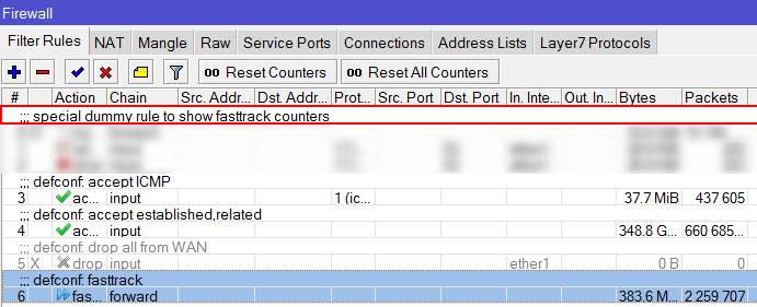
Советы
Хотим так же поделиться парой полезных советов по настройке Firewall:
- Разрешайте только необходимый для работы трафик — да, это сложно. Но методом проб и ошибок мы рекомендуем добиться той настройки фаервола, в рамках которой все ваши подключения будут ясны и понятны.
- Подключения только с определенного пула адресов — это может быть удаленный офис, IP – адреса ЦОД или VPN адресация. Тут нужно быть особенно бдительным.
- В конце правил всегда используйте «deny all» — после того, как вы выполнили первую и вторую рекомендации и весь тип трафика по протоколам, адресации, источникам (в том числе L7, например) четко определен – в конце цепочки добавьте правило запрета всего. Это будет означать, дословно: «Все, что не разрешено — запрещено».
- Атакуйте свою сеть! — да, да, вы не ослышались. Конечно, без фанатизма 🙂 Мы предлагаем периодически сканировать порты на вашем фаерволе. Например, это можно делать с помощью утилиты исследования сети Nmap.
Manual:IP/Firewall/Filter
The firewall implements packet filtering and thereby provides security functions that are used to manage data flow to, from and through the router. Along with the Network Address Translation it serves as a tool for preventing unauthorized access to directly attached networks and the router itself as well as a filter for outgoing traffic.
Network firewalls keep outside threats away from sensitive data available inside the network. Whenever different networks are joined together, there is always a threat that someone from outside of your network will break into your LAN. Such break-ins may result in private data being stolen and distributed, valuable data being altered or destroyed, or entire hard drives being erased. Firewalls are used as a means of preventing or minimizing the security risks inherent in connecting to other networks. Properly configured firewall plays a key role in efficient and secure network infrastrure deployment.
MikroTik RouterOS has very powerful firewall implementation with features including:
- stateful packet inspection
- Layer-7 protocol detection
- peer-to-peer protocols filtering
- traffic classification by:
- source MAC address
- IP addresses (network or list) and address types (broadcast, local, multicast, unicast)
- port or port range
- IP protocols
- protocol options (ICMP type and code fields, TCP flags, IP options and MSS)
- interface the packet arrived from or left through
- internal flow and connection marks
- DSCP byte
- packet content
- rate at which packets arrive and sequence numbers
- packet size
- packet arrival time
- and much more!
Chains
The firewall operates by means of firewall rules. Each rule consists of two parts — the matcher which matches traffic flow against given conditions and the action which defines what to do with the matched packet.
Firewall filtering rules are grouped together in chains. It allows a packet to be matched against one common criterion in one chain, and then passed over for processing against some other common criteria to another chain. For example a packet should be matched against the IP address:port pair. Of course, it could be achieved by adding as many rules with IP address:port match as required to the forward chain, but a better way could be to add one rule that matches traffic from a particular IP address, e.g.: /ip firewall filter add src-address=1.1.1.2/32 jump-target=»mychain» and in case of successfull match passes control over the IP packet to some other chain, id est mychain in this example. Then rules that perform matching against separate ports can be added to mychain chain without specifying the IP addresses.
There are three predefined chains, which cannot be deleted:
- input — used to process packets entering the router through one of the interfaces with the destination IP address which is one of the router’s addresses. Packets passing through the router are not processed against the rules of the input chain
- forward — used to process packets passing through the router
- output — used to process packets originated from the router and leaving it through one of the interfaces. Packets passing through the router are not processed against the rules of the output chain
Packet flow diagrams illustrate how packets are processed in RouterOS.
When processing a chain, rules are taken from the chain in the order they are listed there from top to bottom. If a packet matches the criteria of the rule, then the specified action is performed on it, and no more rules are processed in that chain (the exception is the passthrough action). If a packet has not matched any rule within the built-in chain, then it is accepted.
Properties
- accept — accept the packet. Packet is not passed to next firewall rule.
- add-dst-to-address-list — add destination address to address list specified by address-list parameter
- add-src-to-address-list — add source address to address list specified by address-list parameter
- drop — silently drop the packet
- fasttrack-connection — process packets from a connection using FastPath by enabling FastTrack for the connection
- jump — jump to the user defined chain specified by the value of jump-target parameter
- log — add a message to the system log containing following data: in-interface, out-interface, src-mac, protocol, src-ip:port->dst-ip:port and length of the packet. After packet is matched it is passed to next rule in the list, similar as passthrough
- passthrough — if packet is matched by the rule, increase counter and go to next rule (useful for statistics)
- reject — drop the packet and send an ICMP reject message
- return — passes control back to the chain from where the jump took place
- tarpit — captures and holds TCP connections (replies with SYN/ACK to the inbound TCP SYN packet)
- Value of none-dynamic ( 00:00:00 ) will leave the address in the address list till reboot
- Value of none-static will leave the address in the address list forever and will be included in configuration export/backup
- established — a packet which belongs to an existing connection
- invalid — a packet that does not have determined state in connection tracking (usually — severe out-of-order packets, packets with wrong sequence/ack number, or in case of resource overusage on router), for this reason invalid packet will not participate in NAT (as only connection-state=new packets do), and will still contain original source IP address when routed. We strongly suggest to drop all connection-state=invalid packets in firewall filter forward and input chains
- new — the packet has started a new connection, or otherwise associated with a connection which has not seen packets in both directions.
- related — a packet which is related to, but not part of an existing connection, such as ICMP errors or a packet which begins FTP data connection
- untracked — packet which was set to bypass connection tracking in firewall RAW tables.
- unicast — IP address used for point to point transmission
- local — if dst-address is assigned to one of router’s interfaces
- broadcast — packet is sent to all devices in subnet
- multicast — packet is forwarded to defined group of devices
- count — packet count per time interval per flow to match
- time — specifies the time interval in which the packet count per flow cannot be exceeded (optional, 1s will be used if not specified)
- burst — initial number of packets per flow to match: this number gets recharged by one every time / count , up to this number
- mode — this parameter specifies what unique fields define flow (src-address, dst-address, src-and-dst-address, dst-address-and-port, addresses-and-dst-port)
- expire — specifies interval after which flow with no packets will be allowed to be deleted (optional)
- auth — matches authenticted HotSpot client packets
- from-client — matches packets that are coming from the HotSpot client
- http — matches HTTP requests sent to the HotSpot server
- local-dst — matches packets that are destined to the HotSpot server
- to-client — matches packets that are sent to the HotSpot client
- in — valid in the PREROUTING, INPUT and FORWARD chains
- out — valid in the POSTROUTING, OUTPUT and FORWARD chains
- ipsec — matches if the packet is subject to IpSec processing;
- none — matches packet that is not subject to IpSec processing (for example, IpSec transport packet).
For example, if router receives Ipsec encapsulated Gre packet, then rule ipsec-policy=in,ipsec will match Gre packet, but rule ipsec-policy=in,none will match ESP packet.
- any — match packet with at least one of the ipv4 options
- loose-source-routing — match packets with loose source routing option. This option is used to route the internet datagram based on information supplied by the source
- no-record-route — match packets with no record route option. This option is used to route the internet datagram based on information supplied by the source
- no-router-alert — match packets with no router alter option
- no-source-routing — match packets with no source routing option
- no-timestamp — match packets with no timestamp option
- record-route — match packets with record route option
- router-alert — match packets with router alter option
- strict-source-routing — match packets with strict source routing option
- timestamp — match packets with timestamp
- count — packet or bit count per time interval to match
- time — specifies the time interval in which the packet or bit count cannot be exceeded (optional, 1s will be used if not specified)
- burst — initial number of packets or bits to match: this number gets recharged every 10ms so burst should be at least 1/100 of rate per second
- mode — packet or bit mode
- WeightThreshold — total weight of the latest TCP/UDP packets with different destination ports coming from the same host to be treated as port scan sequence
- DelayThreshold — delay for the packets with different destination ports coming from the same host to be treated as possible port scan subsequence
- LowPortWeight — weight of the packets with privileged ( <1024) destination port
- HighPortWeight — weight of the packet with non-priviliged destination port
Matches source address type:
- unicast — IP address used for point to point transmission
- local — if address is assigned to one of router’s interfaces
- broadcast — packet is sent to all devices in subnet
- multicast — packet is forwarded to defined group of devices
- ack — acknowledging data
- cwr — congestion window reduced
- ece — ECN-echo flag (explicit congestion notification)
- fin — close connection
- psh — push function
- rst — drop connection
- syn — new connection
- urg — urgent data
Stats
/ip firewall filter print stats will show additional read-only properties
| Property | Description |
|---|---|
| bytes (integer) | Total amount of bytes matched by the rule |
| packets (integer) | Total amount of packets matched by the rule |
By default print is equivalent to print static and shows only static rules.
[admin@dzeltenais_burkaans] /ip firewall mangle> print stats Flags: X - disabled, I - invalid, D - dynamic # CHAIN ACTION BYTES PACKETS 0 prerouting mark-routing 17478158 127631 1 prerouting mark-routing 782505 4506
To print also dynamic rules use print all.
[admin@dzeltenais_burkaans] /ip firewall mangle> print all stats Flags: X - disabled, I - invalid, D - dynamic # CHAIN ACTION BYTES PACKETS 0 prerouting mark-routing 17478158 127631 1 prerouting mark-routing 782505 4506 2 D forward change-mss 0 0 3 D forward change-mss 0 0 4 D forward change-mss 0 0 5 D forward change-mss 129372 2031
Or to print only dynamic rules use print dynamic
[admin@dzeltenais_burkaans] /ip firewall mangle> print stats dynamic Flags: X - disabled, I - invalid, D - dynamic # CHAIN ACTION BYTES PACKETS 0 D forward change-mss 0 0 1 D forward change-mss 0 0 2 D forward change-mss 0 0 3 D forward change-mss 132444 2079
Menu specific commands
| Property | Description |
|---|---|
| reset-counters (id) | Reset statistics counters for specified firewall rules. |
| reset-counters-all ( ) | Reset statistics counters for all firewall rules. |
Basic examples
CLI Disctinctive
There is a bit different interpretation in each section with the similar configuration.
For example, with the following configuration line you will match packets where tcp-flags does not have SYN, but has ACK flags:
/ip firewall filter add chain=forward protocol=tcp tcp-flags=!syn,ack
But with this configuration you will match all connections which state is not NEW or RELATED.
/ip firewall filter add action=accept chain=forward connection-state=!new,related
Both configure similarly.
Router protection
Lets say our private network is 192.168.0.0/24 and public (WAN) interface is ether1. We will set up firewall to allow connections to router itself only from our local network and drop the rest. Also we will allow ICMP protocol on any interface so that anyone can ping your router from internet.
/ip firewall filter add chain=input connection-state=invalid action=drop \ comment="Drop Invalid connections" add chain=input connection-state=established action=accept \ comment="Allow Established connections" add chain=input protocol=icmp action=accept \ comment="Allow ICMP" add chain=input src-address=192.168.0.0/24 action=accept \ in-interface=!ether1 add chain=input action=drop comment="Drop everything else"
Customer protection
To protect the customer’s network, we should check all traffic which goes through the router and block unwanted. For icmp, tcp, udp traffic we will create chains, where will be dropped all unwanted packets:
/ip firewall filter add chain=forward protocol=tcp connection-state=invalid \ action=drop comment="drop invalid connections" add chain=forward connection-state=established action=accept \ comment="allow already established connections" add chain=forward connection-state=related action=accept \ comment="allow related connections"
Block «bogon» IP addresses
add chain=forward src-address=0.0.0.0/8 action=drop add chain=forward dst-address=0.0.0.0/8 action=drop add chain=forward src-address=127.0.0.0/8 action=drop add chain=forward dst-address=127.0.0.0/8 action=drop add chain=forward src-address=224.0.0.0/3 action=drop add chain=forward dst-address=224.0.0.0/3 action=drop
Make jumps to new chains:
add chain=forward protocol=tcp action=jump jump-target=tcp add chain=forward protocol=udp action=jump jump-target=udp add chain=forward protocol=icmp action=jump jump-target=icmp
Create tcp chain and deny some tcp ports in it:
add chain=tcp protocol=tcp dst-port=69 action=drop \ comment="deny TFTP" add chain=tcp protocol=tcp dst-port=111 action=drop \ comment="deny RPC portmapper" add chain=tcp protocol=tcp dst-port=135 action=drop \ comment="deny RPC portmapper" add chain=tcp protocol=tcp dst-port=137-139 action=drop \ comment="deny NBT" add chain=tcp protocol=tcp dst-port=445 action=drop \ comment="deny cifs" add chain=tcp protocol=tcp dst-port=2049 action=drop comment="deny NFS" add chain=tcp protocol=tcp dst-port=12345-12346 action=drop comment="deny NetBus" add chain=tcp protocol=tcp dst-port=20034 action=drop comment="deny NetBus" add chain=tcp protocol=tcp dst-port=3133 action=drop comment="deny BackOriffice" add chain=tcp protocol=tcp dst-port=67-68 action=drop comment="deny DHCP"
Deny udp ports in udp chain:
add chain=udp protocol=udp dst-port=69 action=drop comment="deny TFTP" add chain=udp protocol=udp dst-port=111 action=drop comment="deny PRC portmapper" add chain=udp protocol=udp dst-port=135 action=drop comment="deny PRC portmapper" add chain=udp protocol=udp dst-port=137-139 action=drop comment="deny NBT" add chain=udp protocol=udp dst-port=2049 action=drop comment="deny NFS" add chain=udp protocol=udp dst-port=3133 action=drop comment="deny BackOriffice"
Allow only needed icmp codes in icmp chain:
add chain=icmp protocol=icmp icmp-options=0:0 action=accept \ comment="echo reply" add chain=icmp protocol=icmp icmp-options=3:0 action=accept \ comment="net unreachable" add chain=icmp protocol=icmp icmp-options=3:1 action=accept \ comment="host unreachable" add chain=icmp protocol=icmp icmp-options=3:4 action=accept \ comment="host unreachable fragmentation required" add chain=icmp protocol=icmp icmp-options=8:0 action=accept \ comment="allow echo request" add chain=icmp protocol=icmp icmp-options=11:0 action=accept \ comment="allow time exceed" add chain=icmp protocol=icmp icmp-options=12:0 action=accept \ comment="allow parameter bad" add chain=icmp action=drop comment="deny all other types"
other ICMP codes are found here.
Brute force protection
Bandwidth management
This simple firewall filter rule will limit ether1 outgoing traffic to 100Mbps.
/ip firewall filter add action=drop chain=forward out-interface=ether1 limit=!100M,100M:bit
Packet Flow in RouterOS
More advanced firewall setups, or complicated tasks, such as traffic prioritization, routing policies, where it is necessary to utilize more than one RouterOS facility, require knowledge: How do these facilities work together? What happens when and why?
RouterOS packet flow diagram and flow examples will try to answer these questions.
It would be very complicated to represent what is going on with the packet in one diagram, therefore a packet flow diagram is divided into three parts:
- overall diagram;
- detailed bridging, routing, and MPLS flow diagram;
- a diagram that shows what facilities and in what order are included in prerouting, input, forward, output, and postrouting.
Overall Packetflow Diagram
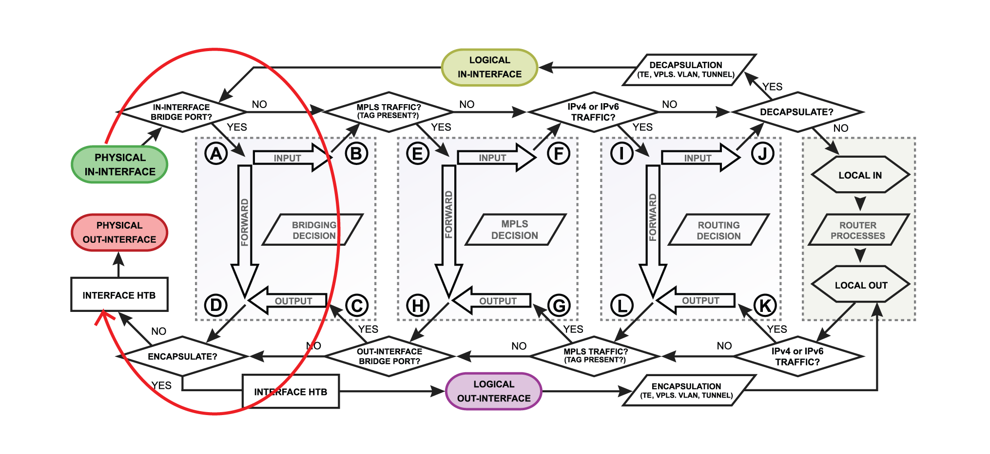
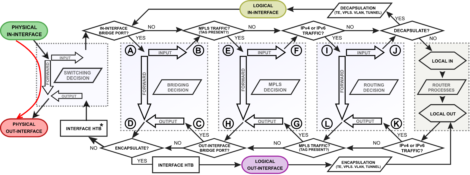
Let’s look at the overall diagram. It looks complicated at first, but after we go through the diagram with examples it will become much clearer.
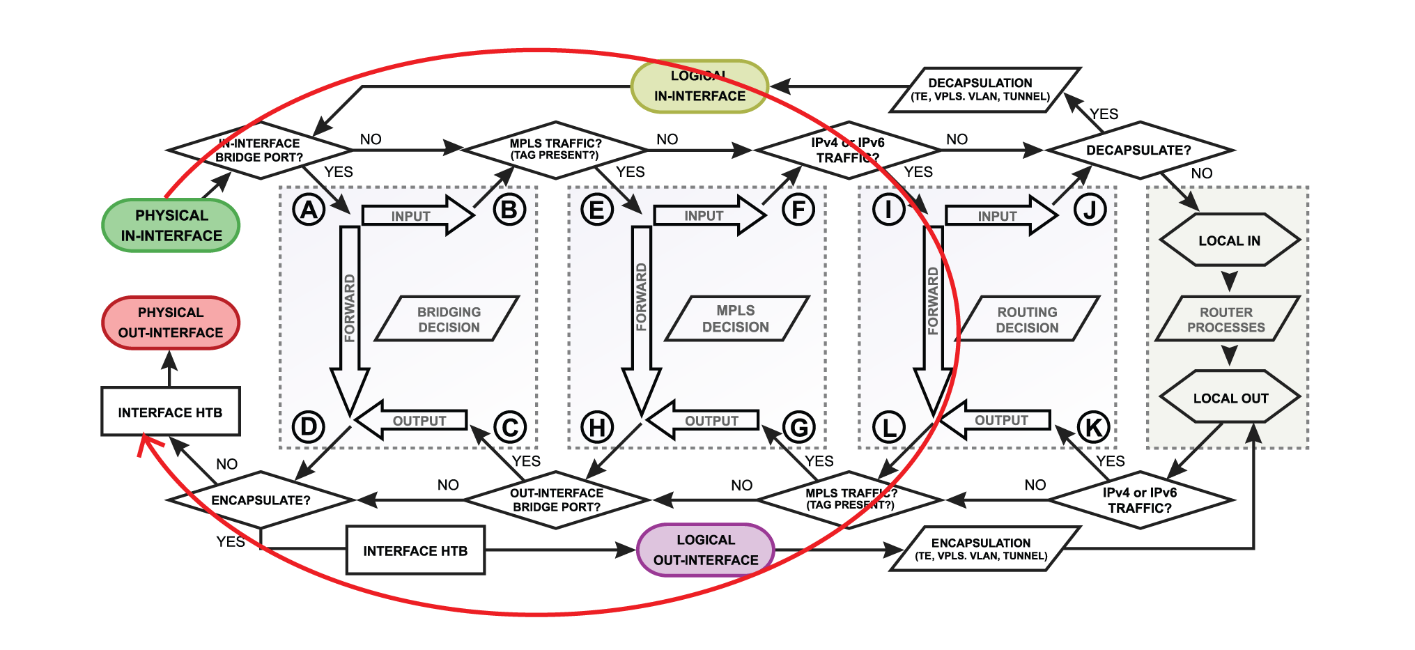
There are 4 boxes in the center of the diagram: Bridging, Routing, Mpls decisions, and local router processes. So for example, if the packet needs to be routed over the router, a packet will flow as illustrated in the image below. Without looking deeper into each facility, the packet enters the in-interface, the router determines that it is IP traffic and needs to be routed, the packet goes through all routing processes and exits the out-interface.
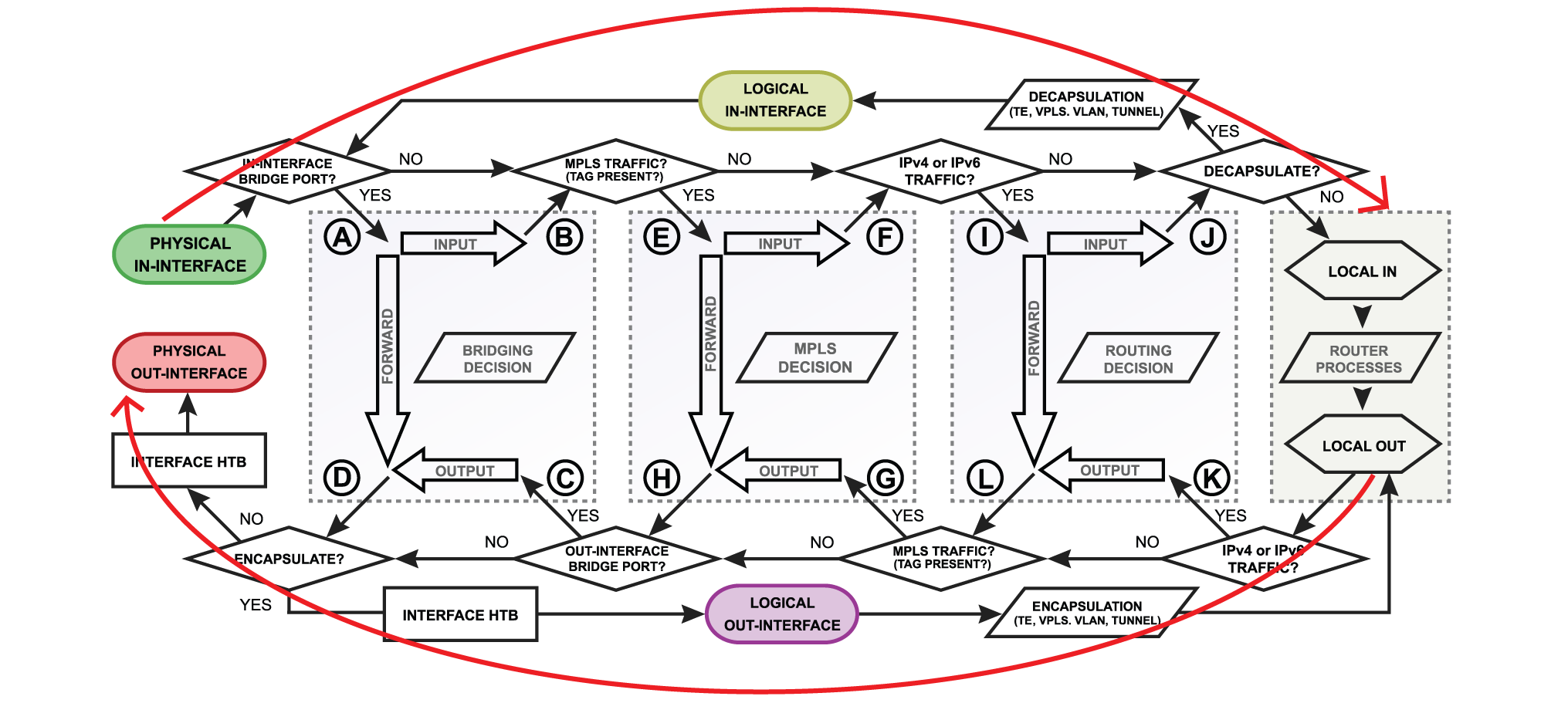
Let’s take a look at another example that will illustrate what happens if the packet’s destination is a router. For example, the in-interface receives ICMP (ping) packet, its destination is the router itself, so the packet will go for local-in processing. After the packet is processed ICMP (ping) reply is generated inside the router (local-out processing) and will be sent out over the out-interface.
A simple explanation of each box before we go further with examples:
- physical in-interface — the starting point of the packet received by the router;
- logical in-interface — the starting point of the decapsulated packet (from tunnels, IPsec, etc);
- local in — the last point of a packet destined to router itself;
- interface HTB (Hierarchical Token Bucket) — interface queue;
- physical out-interface — last point of the packet before it is actually sent out;
- logical out-interface — last point of the packet before encapsulation (to tunnels, IPsec, etc);
- local out — the starting point of a packet generated by the router;
Now it is time to take a deeper look at what is happening inside bridging, MPLS, and routing flows.
A simple explanation of each box before we go further with examples:
- routing decision — go through routes in the routing table to find a match for the destination IP address of the packet. When a match is found — the packet will be processed further, in case of no match — the packet will be discarded.;
- mpls decision — what to do with the packet based on MPLS forwarding tables;
- bridging decision — bridge goes through the MAC address table to find a match for the destination MAC address of the packet. When a match is found — the packet will be processed further, in case of no match — multiple copies of the packet will be created and packets will be flooded (sent out via all bridge ports). A single packet copy will also reach a bridge input chain as the bridge interface itself is one of the many destinations. When using vlan-filtering=yes , packets that are not allowed due to the «/interface bridge vlan» table, will be dropped at this stage.
- use-ip-firewall — whether a ‘use-ip-firewall’ option is enabled in bridge settings;
- ipsec-policy — whether a packet matches any of configured IPsec policies;
Chains
RouterOS consist of a few default chains. These chains allow you to filter packets at various points:
- The PREROUTING chain: Rules in this chain apply to packets as they just arrive on the network interface. This chain is present in the nat, mangle and raw tables.
- The INPUT chain: Rules in this chain apply to packets just before they’re given to a local process. This chain is present in the mangle and filter tables.
- The OUTPUT chain: The rules here apply to packets just after they’ve been produced by a process. This chain is present in the raw, mangle, nat, and filter tables.
- The FORWARD chain: The rules here apply to any packets that are routed through the current host. This chain is only present in the mangle and filter tables.
- The POSTROUTING chain: The rules in this chain apply to packets as they just leave the network interface. This chain is present in the nat and mangle tables.
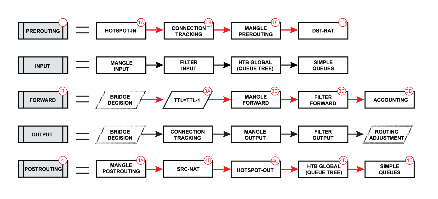
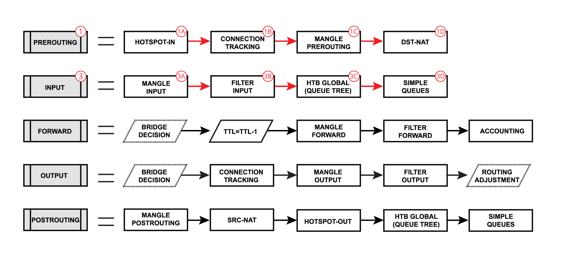
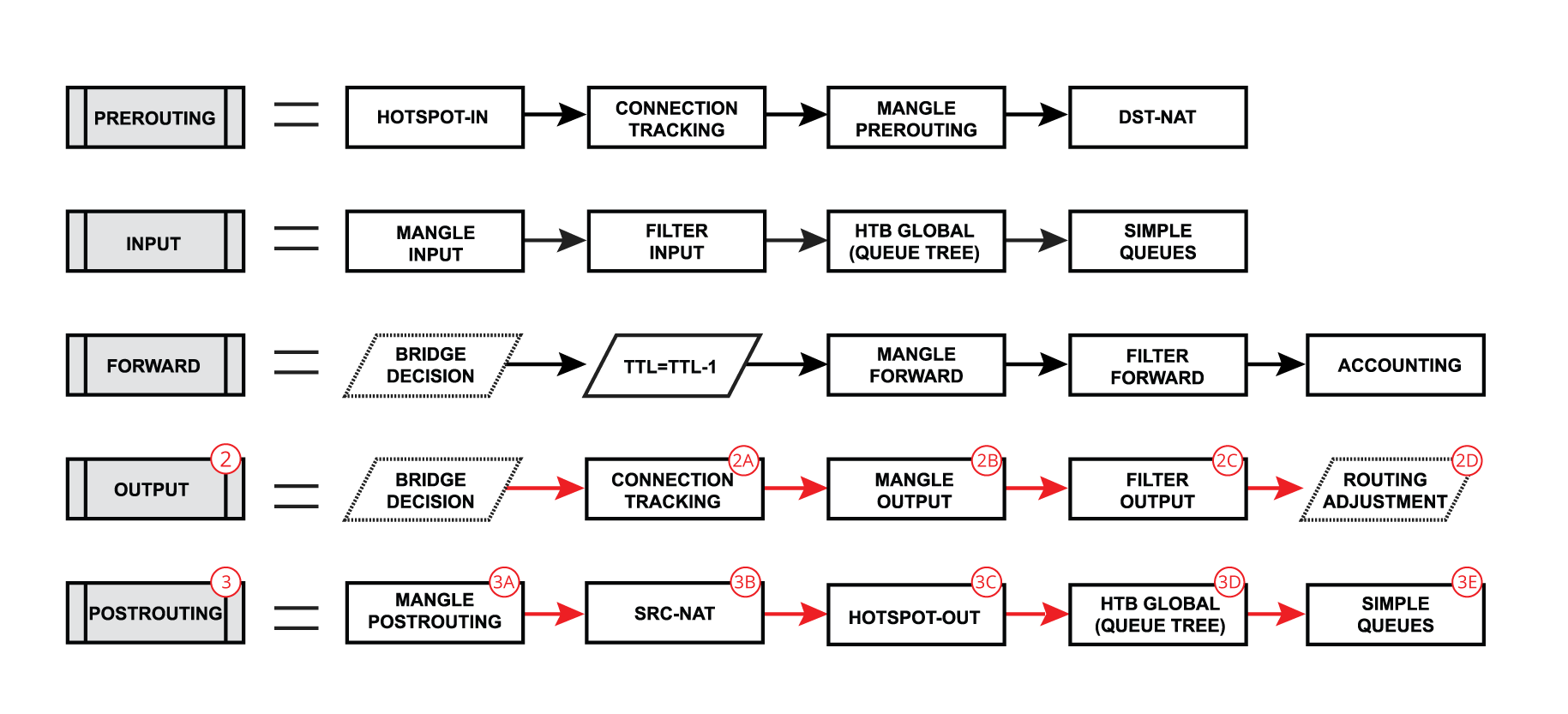
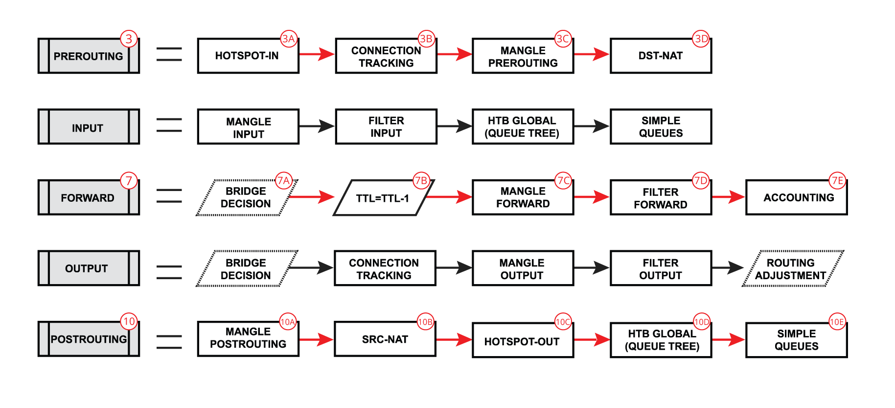
Each of the prerouting, input, forward, output, and postrouting blocks contains even more facilities, which are illustrated in the third part of the packet flow diagram:
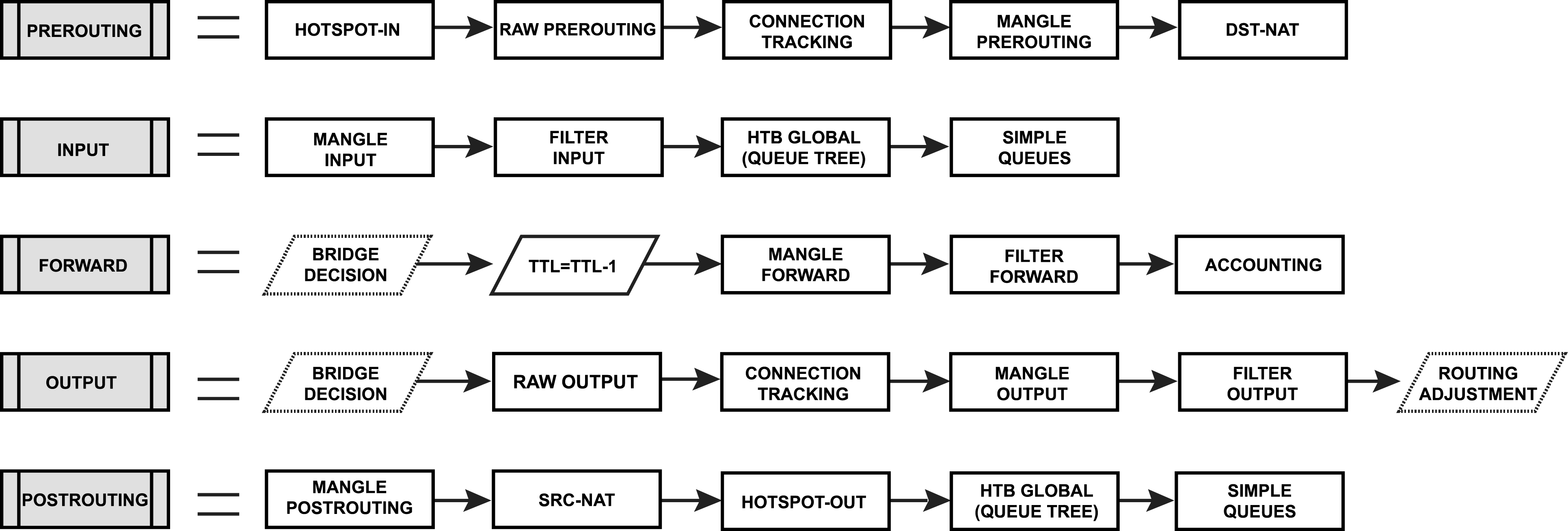
A simple explanation of each box before we go further with examples:
- Hotspot-in — allows to capture traffic that otherwise would be discarded by connection tracking — this way our Hotspot feature is able to provide connectivity even if networks settings are an incomplete mess ;
- RAW Prerouting — RAW table prerouting chain;
- Connection tracking — packet is processed by connection tracking;
- Mangle Prerouting — Mangle prerouting chain;
- Mangle Input — Mangle input chain;
- Filter Input — Firewall filter input chain;
- HTB Global — Queue tree;
- Simple Queues — is a feature that can be used to limit traffic for a particular target ;
- TTL — indicates an exact place where the Time To Live (TTL) of the routed packet is reduced by 1 if TTL becomes 0, a packet will be discarded;
- Mangle Forward — Mangle forward chain;
- Filter Forward — Filter forward chain;
- Accounting — Authentication, Authorization, and Accounting feature processing;
- RAW Output — RAW table output chain;
- Mangle Output — Mangle output chain;
- Filter Output — Firewall filter output chain;
- Routing Adjustment — this is a workaround that allows to set up policy routing in mangle chain output (routing-mark) ;
- Mangle Postrouting — Mangle postrouting chain;
- Src Nat — Network Address Translation srcnat chain;
- Dst Nat — Network Address Translation dstnat chain;
- Hotspot-out — undo all that was done by hotspot-in for the packets that are going back to the client;
Flow of Routed Packet
Forward
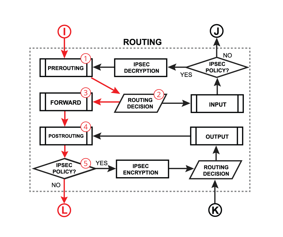
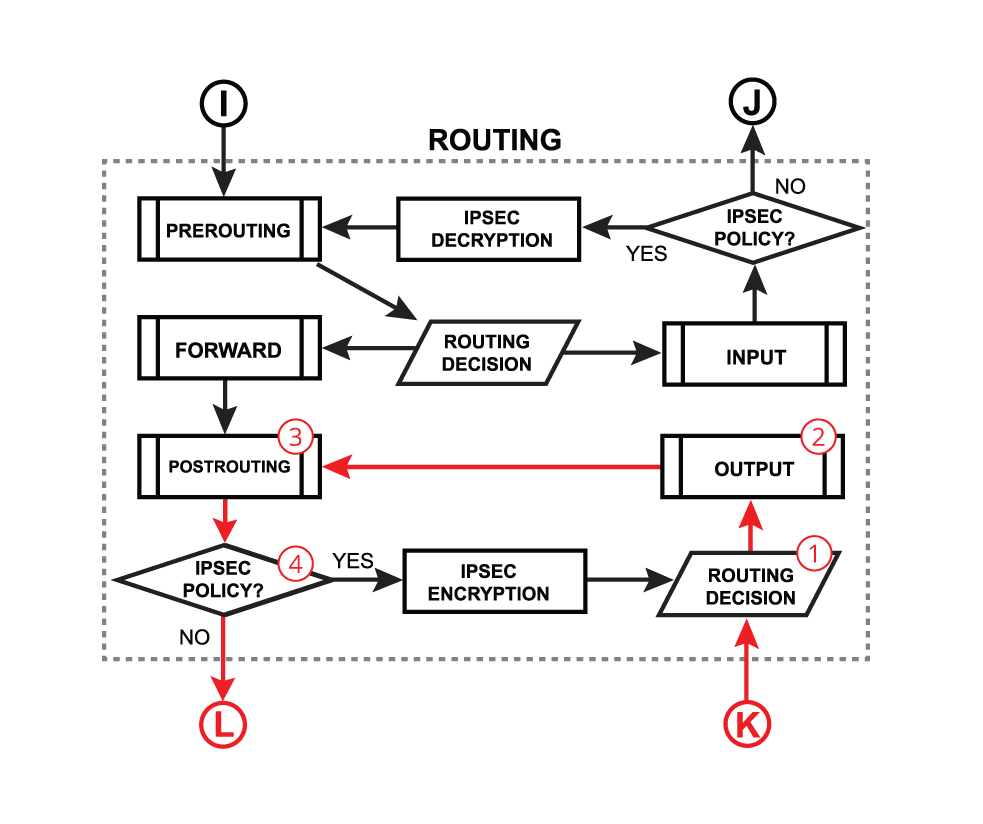
Now, let’s take our first example where the packet gets routed over the router and look deeper through what facilities packet goes:
We already learned that packet goes into the in-interface, the router determines that it is an IP packet and needs to be routed, and here starts the complicated process:
- The packet enters prerouting processing:
- check if there is a hotspot and modify the packet for hotspot use
- process packet through RAW prerouting chain;
- send the packet through connection tracking;
- process packet through Mangle prerouting chain;
- process packet through NATs dst-nat chain;
Input
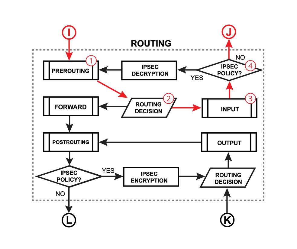
We already learned that packet goes into the in-interface, the router determines that it is an IP packet and needs to be routed, and here starts the complicated process:
- A very similar process happens when a packet’s destination is a router (routing input): Packet enters prerouting processing:
- — check if there is a hotspot and modify the packet for hotspot use;
- — process packet through RAW prerouting chain;
- — send a packet through connection tracking;
- — process packet through Mangle prerouting chain;
- — process packet through NATs dst-nat chain;
- — process packet through Mangle input chain;
- — p rocess packet through Filter input chain;
- — process packet through queue tree (HTB Global);
- — process packet through simple queues;
Output
Or when a packet is originated from the router (routing output):
- The packet is originated from the router itself
- the packet goes through the routing table to make a routing decision
Flow of Bridged Packet
Below is discussed a general bridging process in RouterOS. Most of the packets will always follow the same processing path, but in certain configurations (e.g. with enabled VLAN filtering, horizon, STP, DHCP, or IGMP snooping) some packets can be treated differently. Please visit the bridging manual for more specific information.
Bridge Forward
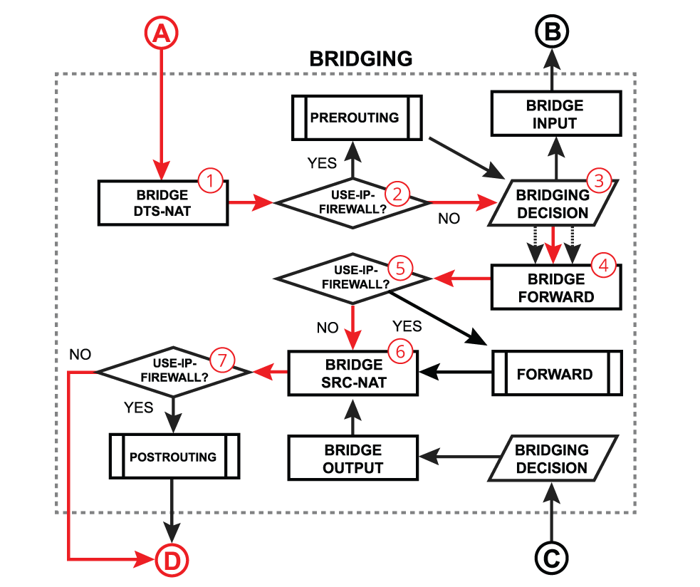
Bridge forward is a process that takes place when a packet is forwarded from one bridge port to another, essentially connecting multiple devices on the same network. After receiving a packet on the in-interface, the device determines that the in-interface is a bridge port, so it gets passed through the bridging process:
- A packet goes through the bridge NAT dst-nat chain, where MAC destination and priority can be changed, apart from that, a packet can be simply accepted, dropped, or marked;
- Checks whether the use-ip-firewall option is enabled in the bridge settings;
- Run packet through the bridge host table to make a forwarding decision. A packet that ends up being flooded (e.g. broadcast, multicast, unknown unicast traffic), gets multiplied per bridge port and then processed further in the bridge forward chain. When using vlan-filtering=yes , packets that are not allowed due to the «/interface bridge vlan» table, will be dropped at this stage.
- A packet goes through the bridge filter forward chain, where priority can be changed or the packet can be simply accepted, dropped, or marked;
- Checks whether the use-ip-firewall option is enabled in the bridge settings;
- A packet goes through the bridge NAT src-nat chain, where MAC source and priority can be changed, apart from that, a packet can be simply accepted, dropped, or marked;
- Checks whether the use-ip-firewall option is enabled in the bridge settings;
For RouterOS v6:
When bridge vlan-filtering is enabled, received untagged packets might get encapsulated into the VLAN header before the «DST-NAT» block, which means these packets can be filtered using the mac-protocol=vlan and vlan-encap settings. Encapsulation can happen if the outgoing interface has frame-types set to admit-all or admit-only-untagged-and-priority-tagged .Tagged packets might get decapsulated on the «BRIDGING DECISION» block, which means these packets will no longer match the mac-protocol=vlan and vlan-encap settings. Decapsulation can happen if the packet’s VLAN ID matches the outgoing port’s untagged VLAN membership.
For RouterOS v7 and newer:
When bridge vlan-filtering is enabled, received untagged packets might get encapsulated into the VLAN header on the «BRIDGING-DECISION» block, which means these packets can be filtered using the mac-protocol=vlan and vlan-encap settings. Encapsulation can happen if the outgoing interface has frame-types set to admit-all or admit-only-untagged-and-priority-tagged .
Tagged packets might get decapsulated on the «BRIDGING DECISION» block, which means these packets will no longer match the mac-protocol=vlan and vlan-encap settings. Decapsulation can happen if the packet’s VLAN ID matches the outgoing port’s untagged VLAN membership.
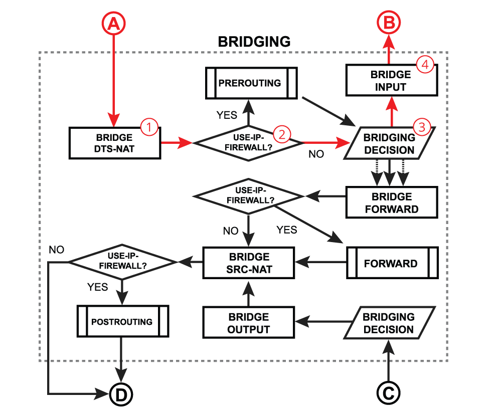
Bridge Input
Bridge input is a process that takes place when a packet is destined for the bridge interface. Most commonly this happens when you need to reach some services that are running on the bridge interface (e.g. a DHCP server) or you need to route traffic to other networks. The very first steps are similar to the bridge forward process — after receiving a packet on the in-interface, the device determines that the in-interface is a bridge port, so it gets passed through the bridging process:
- A packet goes through the bridge NAT dst-nat chain, where MAC destination and priority can be changed, apart from that, a packet can be simply accepted, dropped, or marked;
- Checks whether the use-ip-firewall option is enabled in the bridge settings;
- Run packet through the bridge host table to make a forwarding decision. A packet where the destination MAC address matches the bridge MAC address will be passed to the bridge input chain. A packet that ends up being flooded (e.g. broadcast, multicast, unknown unicast traffic), also reaches the bridge input chain as the bridge interface itself is one of the many destinations;
- A packet goes through the bridge filter input chain, where priority can be changed or the packet can be simply accepted, dropped, or marked;
Bridge Output
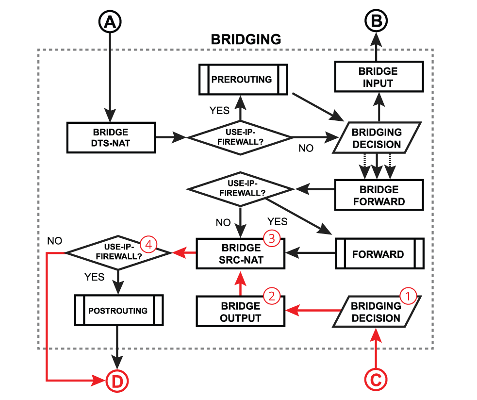
Bridge output is a process that takes place when a packet should exit the device through one or multiple bridge ports. Most commonly this happens when a bridge interface itself tries to reach a device connected to a certain bridge port (e.g. when a DHCP server running on a bridge interface is responding to a DHCP client). After a packet is processed on other higher-level RouterOS processes and the device finally determines that the output interface is a bridge, the packet gets passed through the bridging process:
- Run packet through the bridge host table to make a forwarding decision. A packet that ends up being flooded (e.g. broadcast, multicast, unknown unicast traffic), gets multiplied per bridge port and then processed further in the bridge output chain.
- A packet goes through the bridge filter output chain, where priority can be changed or the packet can be simply accepted, dropped, or marked;
- A packet goes through the bridge NAT src-nat chain, where MAC source and priority can be changed, apart from that, a packet can be simply accepted, dropped, or marked;
- Checks whether the use-ip-firewall option is enabled in the bridge settings;
Forward With Firewall Enabled
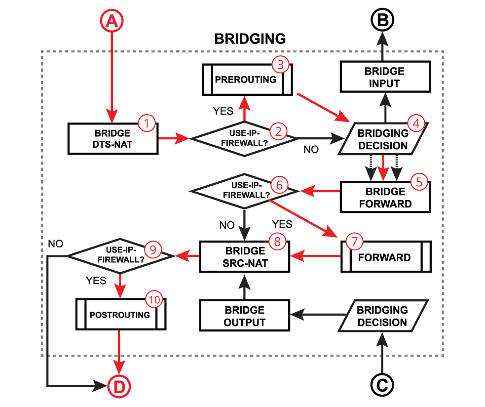
In certain network configurations, you might need to enable additional processing on routing chains for bridged traffic, for example, to use simple queues or an IP firewall. This can be done when the use-ip-firewall is enabled under the bridge settings. Note that additional processing will consume more CPU resources to handle these packets. All the steps were already discussed in previous points, below is a recap:
- A packet goes through the bridge NAT dst-nat chain;
- With the use-ip-firewall option enabled, the packet will be further processed in the prerouting chain;
- A packet enters prerouting processing;
- Run packet through the bridge host table to make forwarding decision;
- A packet goes through the bridge filter forward chain;
- With the use-ip-firewall option enabled, the packet will be further processed in the routing forward chain;
- A packet enters routing forward processing;
- A packet goes through the bridge NAT src-nat chain;
- With the use-ip-firewall option enabled, the packet will be further processed in the postrouting chain;
- A packet enters postrouting processing;
Flow of Hardware Offloaded Packet
On the previous topic, we solely discussed a software bridging that requires the main CPU processing to forward packets through the correct bridge port. Most of the MikroTik devices are equipped with dedicated switching hardware, the so-called switch chip or switch ASIC. This allows us to offload some of the bridging functions, like packet forwarding between bridge ports or packet filtering, to this specialized hardware chip without consuming any CPU resources. In RouterOS, we have named this function Bridge Hardware (HW) Offloading. Different MikroTik devices might have different switch chips and each chip has a different set of features available, so make sure to visit this article to get more details — Bridge Hardware Offloading.
Interface HTB will not work correctly when the out-interface is hardware offloaded and the bridge Fast Path is not active.
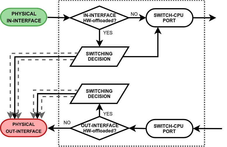
- switching decision — widely depends on the switch model. This block controls all the switching-related tasks, like host learning, packet forwarding, filtering, rate-limiting, VLAN tagging/untagging, mirroring, etc. Certain switch configurations can alter the packet flow;
- switch-cpu port — a special purpose switch port for communication between the main CPU and other switch ports. Note that the switch-cpu port does not show up anywhere on RouterOS except for the switch menu, none of the software-related configurations (e.g. interface-list) can be applied to this port. Packets that reach the CPU are automatically associated with the physical in-interface.
The hardware offloading, however, does not restrict a device to only hardware limited features, rather it is possible to take advantage of the hardware and software processing at the same time. This does require a profound understanding of how packets travel through the switch chip and when exactly they are passed to the main CPU.
Switch Forward
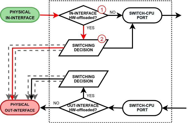
We will further discuss a packet flow when bridge hardware offloading is enabled and a packet is forwarded between two switched ports on a single switch chip. This is the most common and also the simplest example:
- The switch checks whether the in-interface is a hardware offloaded interface;
- Run a packet through the switch host table to make a forwarding decision. If the switch finds a match for the destination MAC address, the packet is sent out through the physical interface. A packet that ends up being flooded (e.g. broadcast, multicast, unknown unicast traffic) gets multiplied and sent out to every hardware offloaded switch port.
Switch to CPU Input
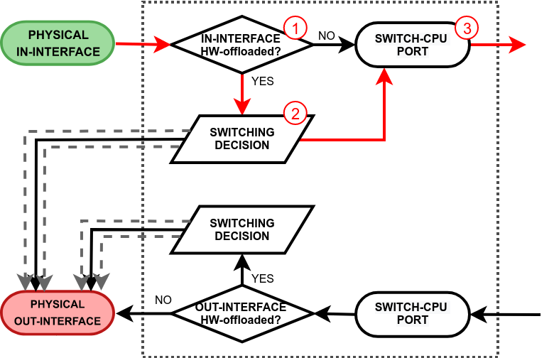
This process takes place when a packet is received on a physical interface and it is destined to switch-cpu port for further software processing. There are two paths to the switch-cpu. One where hardware offloading and switching is not even used (e.g. a standalone interface for routing or a bridged interface but with deliberately disabled HW offloading), so the packet is simply passed further for software processing. Another path is taken when hardware offloading is active on the in-interface. This will cause the packet to pass through the switching decision and there are various reasons why the switch might forward the packet to the switch-cpu port:
- a packet’s destination MAC address match with a local MAC address, e.g. when a packet is destined to a local bridge interface;
- a packet might get flooded to all switch ports including the switch-cpu port, e.g. when broadcast, multicast, or unknown unicast traffic is received;
- a switch might have learned that some hosts can only be reached through the CPU (switch-cpu port learning is discussed in the next section), e.g. when a bridge contains HW and non-HW offloaded interfaces, such as wireless, EoIP, and even Ethernet interfaces;
- a packet is intentionally copied to the switch-cpu, e.g. for a packet inspection;
- a packet is triggered by the switch configuration and should be processed in software, e.g. a DHCP or IGMP snooping.
See the packet walkthrough when an in-interface is hardware offloaded:
- The switch checks whether the in-interface is a hardware offloaded interface;
- Run a packet through the switch host table to make a forwarding decision. In case any of the above-mentioned points are true, the packet gets forwarded to the switch-cpu port.
- The packet exits through the switch-cpu port and it will be further processed by the RouterOS packet flow.
Any received packet that was flooded by the switch chip will not get flooded again by the software bridge to the same HW offloaded switch group. This prevents the formation of duplicate packets.
CPU Output to Switch
This process takes place when a packet exits the RouterOS software processing and is received on the switch-cpu port. Again, there are two paths the packet can take. One where hardware offloading and switching are not even used (e.g. a standalone interface for routing or a bridged interface but with deliberately disabled HW offloading), so the packet is simply sent out through the physical out-interface. Another path is taken when hardware offloading is active on the out-interface. This will cause the packet to pass through the switching decision. Just like any other switch port, the switch will learn the source MAC addresses from packets that are received on the switch-cpu port. This does come in handy when a bridge contains HW and non-HW offloaded interfaces, so the switch can learn which frames should be forwarded to the CPU. See the packet walkthrough when an out-interface is hardware offloaded:
- A packet that exits the RouterOS software processing is received on the switch-cpu port;
- The switch checks whether the out-interface is a hardware offloaded interface;
- Run a packet through the switch host table to make a forwarding decision. If the switch finds a match for the destination MAC address, the packet is sent out through the physical interface. A packet that ends up being flooded (e.g. broadcast, multicast, unknown unicast traffic) gets multiplied and sent out to every hardware offloaded switch port.
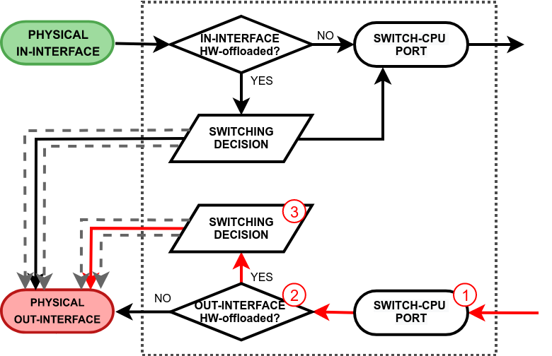
A software bridge that sends a flooded packet through HW offloaded interfaces, will only send a single packet copy per HW offloaded switch group rather than per HW offloaded interface. The actual flooding will be done by the switch chip, this prevents the formation of duplicate packets.