Performance Tuning Network Adapters
Use the information in this topic to tune the performance network adapters for computers that are running Windows Server 2016 and later versions. If your network adapters provide tuning options, you can use these options to optimize network throughput and resource usage.
The correct tuning settings for your network adapters depend on the following variables:
- The network adapter and its feature set
- The type of workload that the server performs
- The server hardware and software resources
- Your performance goals for the server
The following sections describe some of your performance tuning options.
Enabling offload features
Turning on network adapter offload features is usually beneficial. However, the network adapter might not be powerful enough to handle the offload capabilities with high throughput.
Do not use the offload features IPsec Task Offload or TCP Chimney Offload. These technologies are deprecated in Windows Server 2016, and might adversely affect server and networking performance. In addition, these technologies might not be supported by Microsoft in the future.
For example, consider a network adapter that has limited hardware resources. In that case, enabling segmentation offload features might reduce the maximum sustainable throughput of the adapter. However, if the reduced throughput is acceptable, you should go ahead an enable the segmentation offload features.
Some network adapters require you to enable offload features independently for the send and receive paths.
Enabling receive-side scaling (RSS) for web servers
RSS can improve web scalability and performance when there are fewer network adapters than logical processors on the server. When all the web traffic is going through the RSS-capable network adapters, the server can process incoming web requests from different connections simultaneously across different CPUs.
Avoid using both non-RSS network adapters and RSS-capable network adapters on the same server. Because of the load distribution logic in RSS and Hypertext Transfer Protocol (HTTP), performance might be severely degraded if a non-RSS-capable network adapter accepts web traffic on a server that has one or more RSS-capable network adapters. In this circumstance, you should use RSS-capable network adapters or disable RSS on the network adapter properties Advanced Properties tab.
To determine whether a network adapter is RSS-capable, you can view the RSS information on the network adapter properties Advanced Properties tab.
RSS Profiles and RSS Queues
The default RSS predefined profile is NUMAStatic, which differs from the default that the previous versions of Windows used. Before you start using RSS profiles, review the available profiles to understand when they are beneficial and how they apply to your network environment and hardware.
For example, if you open Task Manager and review the logical processors on your server, and they seem to be underutilized for receive traffic, you can try increasing the number of RSS queues from the default of two to the maximum that your network adapter supports. Your network adapter might have options to change the number of RSS queues as part of the driver.
Increasing network adapter resources
For network adapters that allow you to manually configure resources such as receive and send buffers, you should increase the allocated resources.
Some network adapters set their receive buffers low to conserve allocated memory from the host. The low value results in dropped packets and decreased performance. Therefore, for receive-intensive scenarios, we recommend that you increase the receive buffer value to the maximum.
If a network adapter does not expose manual resource configuration, either it dynamically configures the resources, or the resources are set to a fixed value that cannot be changed.
Enabling interrupt moderation
To control interrupt moderation, some network adapters expose different interrupt moderation levels, different buffer coalescing parameters (sometimes separately for send and receive buffers), or both.
You should consider interrupt moderation for CPU-bound workloads. When using interrupt moderation, consider the trade-off between the host CPU savings and latency versus the increased host CPU savings because of more interrupts and less latency. If the network adapter does not perform interrupt moderation, but it does expose buffer coalescing, you can improve performance by increasing the number of coalesced buffers to allow more buffers per send or receive.
Performance tuning for low-latency packet processing
Many network adapters provide options to optimize operating system-induced latency. Latency is the elapsed time between the network driver processing an incoming packet and the network driver sending the packet back. This time is usually measured in microseconds. For comparison, the transmission time for packet transmissions over long distances is usually measured in milliseconds (an order of magnitude larger). This tuning will not reduce the time a packet spends in transit.
Following are some performance tuning suggestions for microsecond-sensitive networks.
- Set the computer BIOS to High Performance, with C-states disabled. However, note that this is system and BIOS dependent, and some systems will provide higher performance if the operating system controls power management. You can check and adjust your power management settings from Settings or by using the powercfg command. For more information, see Powercfg Command-Line Options.
- Set the operating system power management profile to High Performance System.
Note This setting does not work properly if the system BIOS has been set to disable operating system control of power management.
System management interrupts
Many hardware systems use System Management Interrupts (SMI) for a variety of maintenance functions, such as reporting error correction code (ECC) memory errors, maintaining legacy USB compatibility, controlling the fan, and managing BIOS-controlled power settings.
The SMI is the highest-priority interrupt on the system, and places the CPU in a management mode. This mode preempts all other activity while SMI runs an interrupt service routine, typically contained in BIOS.
Unfortunately, this behavior can result in latency spikes of 100 microseconds or more.
If you need to achieve the lowest latency, you should request a BIOS version from your hardware provider that reduces SMIs to the lowest degree possible. These BIOS versions are frequently referred to as «low latency BIOS» or «SMI free BIOS.» In some cases, it is not possible for a hardware platform to eliminate SMI activity altogether because it is used to control essential functions (for example, cooling fans).
The operating system cannot control SMIs because the logical processor is running in a special maintenance mode, which prevents operating system intervention.
Performance tuning TCP
You can use the following items to tune TCP performance.
TCP receive window autotuning
In Windows Vista, Windows Server 2008, and later versions of Windows, the Windows network stack uses a feature that is named TCP receive window autotuning level to negotiate the TCP receive window size. This feature can negotiate a defined receive window size for every TCP communication during the TCP Handshake.
In earlier versions of Windows, the Windows network stack used a fixed-size receive window (65,535 bytes) that limited the overall potential throughput for connections. The total achievable throughput of TCP connections could limit network usage scenarios. TCP receive window autotuning enables these scenarios to fully use the network.
For a TCP receive window that has a particular size, you can use the following equation to calculate the total throughput of a single connection.
Total achievable throughput in bytes = TCP receive window size in bytes * (1 / connection latency in seconds)
For example, for a connection that has a latency of 10 ms, the total achievable throughput is only 51 Mbps. This value is reasonable for a large corporate network infrastructure. However, by using autotuning to adjust the receive window, the connection can achieve the full line rate of a 1-Gbps connection.
Some applications define the size of the TCP receive window. If the application does not define the receive window size, the link speed determines the size as follows:
- Less than 1 megabit per second (Mbps): 8 kilobytes (KB)
- 1 Mbps to 100 Mbps: 17 KB
- 100 Mbps to 10 gigabits per second (Gbps): 64 KB
- 10 Gbps or faster: 128 KB
For example, on a computer that has a 1-Gbps network adapter installed, the window size should be 64 KB.
This feature also makes full use of other features to improve network performance. These features include the rest of the TCP options that are defined in RFC 1323. By using these features, Windows-based computers can negotiate TCP receive window sizes that are smaller but are scaled at a defined value, depending on the configuration. This behavior the sizes easier to handle for networking devices.
You may experience an issue in which the network device is not compliant with the TCP window scale option, as defined in RFC 1323 and, therefore, doesn’t support the scale factor. In such cases, refer to this KB 934430, Network connectivity fails when you try to use Windows Vista behind a firewall device or contact the Support team for your network device vendor.
Review and configure TCP receive window autotuning level
You can use either netsh commands or Windows PowerShell cmdlets to review or modify the TCP receive window autotuning level.
Unlike in versions of Windows that pre-date Windows 10 or Windows Server 2019, you can no longer use the registry to configure the TCP receive window size. For more information about the deprecated settings, see Deprecated TCP parameters.
For detailed information about the available autotuning levels, see Autotuning levels.
To use netsh to review or modify the autotuning level
To review the current settings, open a Command Prompt window and run the following command:
netsh interface tcp show global The output of this command should resemble the following:
Querying active state. TCP Global Parameters ----- Receive-Side Scaling State : enabled Chimney Offload State : disabled Receive Window Auto-Tuning Level : normal Add-On Congestion Control Provider : default ECN Capability : disabled RFC 1323 Timestamps : disabled Initial RTO : 3000 Receive Segment Coalescing State : enabled Non Sack Rtt Resiliency : disabled Max SYN Retransmissions : 2 Fast Open : enabled Fast Open Fallback : enabled Pacing Profile : off To modify the setting, run the following command at the command prompt:
netsh interface tcp set global autotuninglevel=
In the preceding command, Value> represents the new value for the auto tuning level.
To use Powershell to review or modify the autotuning level
To review the current settings, open a PowerShell window and run the following cmdlet.
Get-NetTCPSetting | Select SettingName,AutoTuningLevelLocal The output of this cmdlet should resemble the following.
SettingName AutoTuningLevelLocal ----------- -------------------- Automatic InternetCustom Normal DatacenterCustom Normal Compat Normal Datacenter Normal Internet Normal To modify the setting, run the following cmdlet at the PowerShell command prompt.
Set-NetTCPSetting -AutoTuningLevelLocal
In the preceding command, Value> represents the new value for the auto tuning level.
For more information about these cmdlets, see the following articles:
Autotuning levels
You can set receive window autotuning to any of five levels. The default level is Normal. The following table describes the levels.
| Level | Hexadecimal value | Comments |
|---|---|---|
| Normal (default) | 0x8 (scale factor of 8) | Set the TCP receive window to grow to accommodate almost all scenarios. |
| Disabled | No scale factor available | Set the TCP receive window at its default value. |
| Restricted | 0x4 (scale factor of 4) | Set the TCP receive window to grow beyond its default value, but limit such growth in some scenarios. |
| Highly Restricted | 0x2 (scale factor of 2) | Set the TCP receive window to grow beyond its default value, but do so very conservatively. |
| Experimental | 0xE (scale factor of 14) | Set the TCP receive window to grow to accommodate extreme scenarios. |
If you use an application to capture network packets, the application should report data that resembles the following for different window autotuning level settings.
-
Autotuning level: Normal (default state)
Frame: Number = 492, Captured Frame Length = 66, MediaType = ETHERNET + Ethernet: Etype = Internet IP (IPv4),DestinationAddress:[D8-FE-E3-65-F3-FD],SourceAddress:[C8-5B-76-7D-FA-7F] + Ipv4: Src = 192.169.0.5, Dest = 192.169.0.4, Next Protocol = TCP, Packet Total IP Length = 52 - Tcp: [Bad CheckSum]Flags=. S., SrcPort=60975, DstPort=Microsoft-DS(445), PayloadLen=0, Seq=4075590425, Ack=0, Win=64240 ( Negotiating scale factor 0x8 ) = 64240 SrcPort: 60975 DstPort: Microsoft-DS(445) SequenceNumber: 4075590425 (0xF2EC9319) AcknowledgementNumber: 0 (0x0) + DataOffset: 128 (0x80) + Flags: . S. ---------------------------------------------------------> SYN Flag set Window: 64240 ( Negotiating scale factor 0x8 ) = 64240 ---------> TCP Receive Window set as 64K as per NIC Link bitrate. Note it shows the 0x8 Scale Factor. Checksum: 0x8182, Bad UrgentPointer: 0 (0x0) - TCPOptions: + MaxSegmentSize: 1 + NoOption: + WindowsScaleFactor: ShiftCount: 8 -----------------------------> Scale factor, defined by AutoTuningLevel + NoOption: + NoOption: + SACKPermitted: Frame: Number = 353, Captured Frame Length = 62, MediaType = ETHERNET + Ethernet: Etype = Internet IP (IPv4),DestinationAddress:[D8-FE-E3-65-F3-FD],SourceAddress:[C8-5B-76-7D-FA-7F] + Ipv4: Src = 192.169.0.5, Dest = 192.169.0.4, Next Protocol = TCP, Packet Total IP Length = 48 - Tcp: [Bad CheckSum]Flags=. S., SrcPort=60956, DstPort=Microsoft-DS(445), PayloadLen=0, Seq=2315885330, Ack=0, Win=64240 ( ) = 64240 SrcPort: 60956 DstPort: Microsoft-DS(445) SequenceNumber: 2315885330 (0x8A099B12) AcknowledgementNumber: 0 (0x0) + DataOffset: 112 (0x70) + Flags: . S. ---------------------------------------------------------> SYN Flag set Window: 64240 ( ) = 64240 ----------------------------------------> TCP Receive Window set as 64K as per NIC Link bitrate. Note there is no Scale Factor defined. In this case, Scale factor is not being sent as a TCP Option, so it will not be used by Windows. Checksum: 0x817E, Bad UrgentPointer: 0 (0x0) - TCPOptions: + MaxSegmentSize: 1 + NoOption: + NoOption: + SACKPermitted: Frame: Number = 3, Captured Frame Length = 66, MediaType = ETHERNET + Ethernet: Etype = Internet IP (IPv4),DestinationAddress:[D8-FE-E3-65-F3-FD],SourceAddress:[C8-5B-76-7D-FA-7F] + Ipv4: Src = 192.169.0.5, Dest = 192.169.0.4, Next Protocol = TCP, Packet Total IP Length = 52 - Tcp: [Bad CheckSum]Flags=. S., SrcPort=60890, DstPort=Microsoft-DS(445), PayloadLen=0, Seq=1966088568, Ack=0, Win=64240 ( Negotiating scale factor 0x4 ) = 64240 SrcPort: 60890 DstPort: Microsoft-DS(445) SequenceNumber: 1966088568 (0x75302178) AcknowledgementNumber: 0 (0x0) + DataOffset: 128 (0x80) + Flags: . S. ---------------------------------------------------------> SYN Flag set Window: 64240 ( Negotiating scale factor 0x4 ) = 64240 ---------> TCP Receive Window set as 64K as per NIC Link bitrate. Note it shows the 0x4 Scale Factor. Checksum: 0x8182, Bad UrgentPointer: 0 (0x0) - TCPOptions: + MaxSegmentSize: 1 + NoOption: + WindowsScaleFactor: ShiftCount: 4 -------------------------------> Scale factor, defined by AutoTuningLevel. + NoOption: + NoOption: + SACKPermitted: Frame: Number = 115, Captured Frame Length = 66, MediaType = ETHERNET + Ethernet: Etype = Internet IP (IPv4),DestinationAddress:[D8-FE-E3-65-F3-FD],SourceAddress:[C8-5B-76-7D-FA-7F] + Ipv4: Src = 192.169.0.5, Dest = 192.169.0.4, Next Protocol = TCP, Packet Total IP Length = 52 - Tcp: [Bad CheckSum]Flags=. S., SrcPort=60903, DstPort=Microsoft-DS(445), PayloadLen=0, Seq=1463725706, Ack=0, Win=64240 ( Negotiating scale factor 0x2 ) = 64240 SrcPort: 60903 DstPort: Microsoft-DS(445) SequenceNumber: 1463725706 (0x573EAE8A) AcknowledgementNumber: 0 (0x0) + DataOffset: 128 (0x80) + Flags: . S. ---------------------------------------------------------> SYN Flag set Window: 64240 ( Negotiating scale factor 0x2 ) = 64240 ---------> TCP Receive Window set as 64K as per NIC Link bitrate. Note it shows the 0x2 Scale Factor. Checksum: 0x8182, Bad UrgentPointer: 0 (0x0) - TCPOptions: + MaxSegmentSize: 1 + NoOption: + WindowsScaleFactor: ShiftCount: 2 ------------------------------> Scale factor, defined by AutoTuningLevel + NoOption: + NoOption: + SACKPermitted: Frame: Number = 238, Captured Frame Length = 66, MediaType = ETHERNET + Ethernet: Etype = Internet IP (IPv4),DestinationAddress:[D8-FE-E3-65-F3-FD],SourceAddress:[C8-5B-76-7D-FA-7F] + Ipv4: Src = 192.169.0.5, Dest = 192.169.0.4, Next Protocol = TCP, Packet Total IP Length = 52 - Tcp: [Bad CheckSum]Flags=. S., SrcPort=60933, DstPort=Microsoft-DS(445), PayloadLen=0, Seq=2095111365, Ack=0, Win=64240 ( Negotiating scale factor 0xe ) = 64240 SrcPort: 60933 DstPort: Microsoft-DS(445) SequenceNumber: 2095111365 (0x7CE0DCC5) AcknowledgementNumber: 0 (0x0) + DataOffset: 128 (0x80) + Flags: . S. ---------------------------------------------------------> SYN Flag set Window: 64240 ( Negotiating scale factor 0xe ) = 64240 ---------> TCP Receive Window set as 64K as per NIC Link bitrate. Note it shows the 0xe Scale Factor. Checksum: 0x8182, Bad UrgentPointer: 0 (0x0) - TCPOptions: + MaxSegmentSize: 1 + NoOption: + WindowsScaleFactor: ShiftCount: 14 -----------------------------> Scale factor, defined by AutoTuningLevel + NoOption: + NoOption: + SACKPermitted: Deprecated TCP parameters
The following registry settings from Windows Server 2003 are no longer supported, and are ignored in later versions.
All of these settings were located in the following registry subkey:
HKEY_LOCAL_MACHINE\System\CurrentControlSet\Services\Tcpip\Parameters
Windows Filtering Platform
Windows Vista and Windows Server 2008 introduced the Windows Filtering Platform (WFP). WFP provides APIs to non-Microsoft independent software vendors (ISVs) to create packet processing filters. Examples include firewall and antivirus software.
A poorly-written WFP filter can significantly decrease a server’s networking performance. For more information, see Porting Packet-Processing Drivers and Apps to WFP in the Windows Dev Center.
For links to all topics in this guide, see Network Subsystem Performance Tuning.
Known issues of TCP/IP performance
This article describes the following TCP/IP performance issues:
- Slow throughput on high latency and high bandwidth network
- Slow throughput on low latency and high bandwidth network
- Underlying network issues
Slow throughput speed on a high latency and bandwidth network
Two servers located in different sites are connected over a high latency network. The throughput measured with the ctsTraffic tool is lower than the baseline.
That’s because the TCP Window Scale option isn’t enabled on either server. Use Windows Command Prompt or Windows PowerShell to enable the option by setting the TCP receive window autotuning level.
Use Command Prompt to enable the autotuning level
Run the following command:
netsh int tcp set global autotuninglevel=normal To check if the autotuning level is enabled, use the following command:
netsh int tcp show global 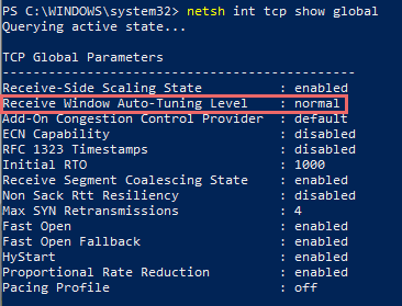
Use PowerShell to enable the autotuning level
Run the following cmdlet:
Get-NetTCPSetting | Set-NetTCPSetting -AutoTuningLevelLocal Normal To check if the autotuning level is enabled, use the following cmdlet:
Get-NetTCPSetting | Format-List SettingName,Autotuninglevel* 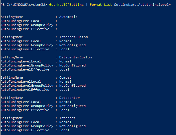
There are five levels for receive window autotuning: Disabled, Highly Restricted, Restricted, Normal, and Experimental. For more information about how autotuning affects the throughput, see Performance Tuning Network Adapters.
Slow throughput speed on a low latency and high bandwidth network
Two servers are connected on a same network that has low latency and high bandwidth. When you create a baseline or test TCP performance with the ctsTraffic tool, only CPU 0 spikes in a multi-core CPU server.
This issue occurs because the Receive Side Scaling (RSS) or Virtual Machine Queue (VMQ) feature isn’t enabled or isn’t configured correctly. Use VMQ when the physical machine is a hypervisor. If it isn’t, enable RSS on both the Operating System (OS) and on the network cards.
Wireless network cards don’t support RSS or VMQ features.
Enable RSS for OS
Enable RSS by using Command Prompt or PowerShell as follows:
Command Prompt: netsh int tcp set global rss=enabled
PowerShell: Set-NetAdapterRss -Name -Enabled $True
Enable RSS for network cards
First, check if the RSS feature is enabled. Check the network card advanced properties for the related configuration by using the following cmdlet:
Get-NetAdapterAdvancedProperty | Where-Object -property RegistryKeyword -Like *rss* | format-table -AutoSize Changes to the advanced properties may result in interruption or loss of network connectivity. Before making the changes, refer to the NIC vendor documentation.
Follow these steps to enable RSS for network cards:
- Run ncpa.cpl to open Network Connections.
- Right-click the targeted connection, and then select Properties >Configure.
- Under the Advanced tab, locate Receive Side Scaling in the Property list and then set the Value to Enable.
- Select OK.
RSS can also be enabled by using the PowerShell cmdlet:
Set-NetAdapterAdvancedProperty -Name -RegistryKeyword *RSS -RegistryValue 1 Underlying network issues
This section describes how to check for underlying network issues while measuring a throughput baseline or troubleshooting throughput issues.
To get a packet level log analysis, check underlying network issues by using a network packet capturing tool (such as Microsoft Network Monitor, Wireshark, or ctsTraffic).
Steps to take logs with network packet capturing tools
- Start logging with Microsoft Network Monitor or Wireshark to capture traffic on both endpoints. You can also use the Windows built-in capturing tool as follows:
- Open Command Prompt as an administrator.
- Run the following command:
NETSH TRACE START CAPTURE=YES REPORT=DISABLED TRACEFILE=.ETL MAXSIZE=512Note Multiple captures might be required while using the netsh trace command.
Analyze the capture file
Here’s an example showing how to analyze a filtered result. In this scenario, the ctsTraffic tool uses the push pattern (the default pattern), which means the packet is sent from the client to the server.
- Open the capture file in Microsoft Network Monitor.
- Filter the network trace by using the Property.TCPRetransmit==1 && tcp.Port==4444 filter, which locates the retransmission packets. A packet retransmission means that a TCP acknowledgment of the given TCP sequence from the sender is never received.
Note To analyze an ETL file, go to Tools > Options > Parser Profiles > Windows > Set As Active > OK.
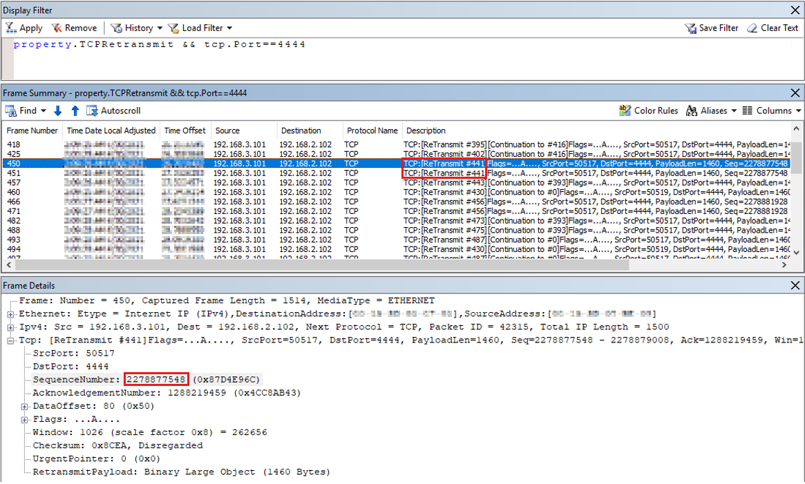 As shown in the screenshot, frame #441 is retransmitted twice, which means it is transmitted by the sender three times. Use the same TCP sequence number (2278877548) to identify this frame.
 - Right-click the SequenceNumber in Frame Details and select Add Selected Value to Display Filter.
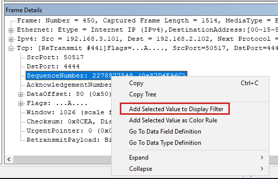
- Disable the previous filter by adding «//» as follows:

- Select Apply. The complete TCP sequence with this sequence number is displayed as follows:
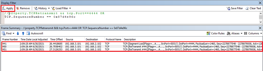 This result shows that the original frame #441 isn’t received by the server and is retransmitted by the sender. The retransmission of a frame happens if no acknowledgment of the sequence is received. To understand how TCP works, see The three-way handshake via TCP/IP and Description of Windows TCP features. Then, copy the TCP.SequenceNumber == sequence filter from the client trace and paste it on the server trace. On the server, only one packet of the given sequence is received, as shown in the following result:
 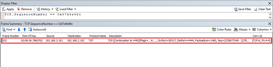 This result proves that there is packet loss from the sender to the receiver on the intermediate network devices. The packets leave the sender but never reach the receiver. It is an issue with underlying networking and it should be resolved by network administrators.
TCP Loopback Performance
With the Release of Windows Server 2019, the TCP/IP loopback processing model has been changed in order to address certain performance bottlenecks which existed in previous windows releases. This section describes the configuration options available to change the behavior of TCP/IP loopback processing.
The configuration parameters are available through the netsh configuration tool. Each setting can be set individually for IPv4 and IPv6. The default values might vary from different Windows versions.
On general purpose Windows computers, the default values should not be changed.
If a application developer determines that the loopback data path is the root cause for the applications insufficient performance, the following commands can be used to tailor the configuration towards the individual needs of the application.
netsh int ipv6|ipv4 set gl loopbackexecutionmode=adaptive|inline|worker netsh int ipv6|ipv4 set gl loopbackworkercount= netsh int ipv6|ipv4 set gl loopbacklargemtu=enable|disable Explanation
Loopbackexecutionmode Worker In this mode, packets are queued on the send side and processed by a worker thread on the receive side. This mode favors throughput over latency.
Inline In this mode, processing is done in context of application threads both on sender and receiver side. This mode favors latency over throughput.
Adaptive First packets of the data flow are processing inline,and then packets are deferred to workerthread. This mode tries to balance latency and throughput.
Loopbackworkercount Allows to configure the number of workerthreads been used.
Loopbacklargemtu Allows to configure the use of large MTU, this should enabled.
Windows может ограничивать скорость подключения к Интернету — Как исправить
Инструкция может быть также полезна для случаев, когда вы были довольны скоростью подключения при использовании предыдущих версий Windows, но заметили замедление после обновления до Windows 10 “Юбилейное обновление”.
Microsoft представила функцию «автонастройка окна получения» (Window Auto-Tuning) еще в Windows Vista. Инструмент предназначен для улучшения производительности программ, которые получают данные из сети по протоколу TCP.
Несмотря на то, что передача данных должна стать более эффективной, пользователи могут столкнуться со снижением скорости соединения при определенных обстоятельствах и даже с проблемами стабильности канала связи.
Настраиваем Window Auto-Tuning в Windows 10
Прежде всего, следует проверить статус функции автонастройки окна получения. Если она отключена, то очевидно, что она не является причиной низкой скорости Интернета. Однако, в противном случае, именно эта функция ;может стать виновником медленного интернет соединения.
Примечание: для работы командной строки ниже не требуются права администратора, но для изменения параметров повышенные привилегии потребуются.
- Нажмите правой кнопкой мыши на значок меню Пуск и выберите «Командная строка (администратор)».
- Подтвердите запрос службы контроля учетных записей
- Запустите команду netsh interface tcp show global

Обратите внимание на параметр “Уровень автонастройки окна получения” в разделе Глобальные параметры TCP. Если значение параметра отличается от “disabled”, то функция используется Windows для оптимизации TCP-подключений.
Логичным решением будет отключение данной функции и проведение тестов скорости Интернета, чтобы выявить, является ли она причиной снижения пропускной способности.
Запустите следующую команду для отключения функции автонастройки окна получения:
netsh int tcp set global autotuninglevel=disabled
Вы получите подтверждение OK о том, что изменение было успешно внесено. При повторном запуске команды netsh interface tcp show global будет наглядно видно, что функция отключена.

После отключения функции запустите загрузки и выполните мониторинг получаемых скоростей. Для тестирования следует использовать P2P-клиенты, Usenet-клиенты, FTP-клиенты, серверные программы и т.д.
Если ничего не изменилось, можно восстановить исходные настройки с помощью команды:
netsh int tcp set global autotuninglevel=normal
Должно вернуться подтверждение успешного завершения операции — ОК. Проверьте глобальные параметры TCP, чтобы убедиться в изменении.
Настройка производительности сетевых адаптеров
Используйте сведения в этом разделе, чтобы настроить сетевые адаптеры производительности для компьютеров под управлением Windows Server 2016 и более поздних версий. Если сетевые адаптеры предоставляют параметры настройки, эти параметры можно использовать для оптимизации пропускной способности сети и использования ресурсов.
Правильные параметры настройки сетевых адаптеров зависят от следующих переменных:
- сетевой адаптер и набор его функций;
- Тип рабочей нагрузки, выполняемой сервером
- аппаратные и программные ресурсы сервера;
- задачи настройки сервера.
В следующих разделах описывается ряд параметров настройки производительности.
Включение функций разгрузки
Включение функций разгрузки на сетевом адаптере обычно имеет положительный эффект. Однако сетевой адаптер может быть недостаточно мощным для обработки возможностей разгрузки с высокой пропускной способностью.
Не используйте функции разгрузки IPsec Task Offload или TCP Chimney Offload. Эти технологии устарели в Windows Server 2016 и могут негативно повлиять на производительность сервера и сети. Кроме того, эти технологии могут не поддерживаться корпорацией Майкрософт в будущем.
Например, рассмотрим сетевой адаптер, имеющий ограниченные аппаратные ресурсы. В этом случае включение функций разгрузки сегментации может снизить максимальную устойчивую пропускную способность адаптера. Однако если сниженная пропускная способность допустима, следует включить функции разгрузки сегментации.
Для некоторых сетевых адаптеров требуется включить функции разгрузки независимо от пути отправки и получения.
Включение масштабирования на стороне получения (RSS) для веб-серверов
RSS способно повысить веб-масштабируемость и производительность, когда число сетевых адаптеров меньше количества логических процессоров на сервере. Когда весь веб-трафик проходит через сетевые адаптеры с поддержкой RSS, сервер может обрабатывать входящие веб-запросы из разных подключений одновременно по разным ЦП.
Избегайте использования сетевых адаптеров, отличных от RSS, и сетевых адаптеров с поддержкой RSS на одном сервере. Из-за логики распределения нагрузки в RSS и протоколе http производительность может быть значительно снижена, если сетевой адаптер, не поддерживающий RSS, принимает веб-трафик на сервере с одним или несколькими сетевыми адаптерами с поддержкой RSS. В этом случае следует использовать сетевые адаптеры с поддержкой RSS или отключить RSS на вкладке «Дополнительные свойства сетевого адаптера».
Чтобы определить, поддерживается ли сетевой адаптер RSS, можно просмотреть сведения о RSS на вкладке «Дополнительные свойства сетевого адаптера».
Профили RSS и очереди RSS
Стандартный профиль RSS — NUMAStatic, который отличается от используемого по умолчанию предыдущих версий Windows. Прежде чем приступить к использованию профилей RSS, просмотрите доступные профили, чтобы понять, когда они полезны и как они применяются к сетевой среде и оборудованию.
Например, если открыть диспетчер задач и просмотреть логические процессоры на сервере, и они, как представляется, недостаточно используются для получения трафика, можно попробовать увеличить количество очередей RSS по умолчанию до максимального, что поддерживает сетевой адаптер. В используемом сетевом адаптере могут быть параметры для изменения числа очередей RSS в драйвере.
Увеличение ресурсов сетевого адаптера
Для сетевых адаптеров, которые позволяют вручную настраивать ресурсы, такие как получение и отправка буферов, следует увеличить выделенные ресурсы.
В некоторых сетевых адаптерах устанавливаются небольшие буферы приема для экономии выделенной памяти от узла. Это ведет к потере пакетов и снижению производительности. Поэтому для сценариев с интенсивным приемом рекомендуется увеличить буфер приема до максимума.
Если сетевой адаптер не предоставляет конфигурацию ресурсов вручную, он динамически настраивает ресурсы или ресурсы задаются в фиксированное значение, которое невозможно изменить.
Включение модерации прерываний
Для управления модерацией прерываний некоторые сетевые адаптеры предоставляют различные уровни модерации прерываний, различные параметры объединения буферов (иногда отдельно для буферов отправки и получения) или обоих.
Следует рассмотреть возможность модерации прерываний для рабочих нагрузок, связанных с ЦП. При использовании модерации прерываний рассмотрите компромисс между экономией ЦП узла и задержкой и увеличением экономии ЦП узла из-за большего количества прерываний и меньшей задержки. Если сетевой адаптер не выполняет модерацию прерываний, но он предоставляет объединение буферов, можно повысить производительность, увеличив число объединенных буферов, чтобы разрешить больше буферов на отправку или получение.
Настройка производительности для обработки пакетов с низкой задержкой
Многие сетевые адаптеры позволяют настраивать параметры для оптимизации системной задержки. Задержка — это время между обработкой входящего пакета сетевым драйвером и отправкой этого пакета обратно. Обычно это время измеряется в микросекундах. Для сравнения время передачи пакетов на длинные расстояния обычно измеряется в миллисекундах (порядка величины больше). Эта настройка не сокращает время прохождения пакета.
Ниже приведены некоторые советы по настройке производительности для загруженных сетей, в которых на счету каждая микросекунда.
- Установите для компьютера BIOS высокий уровень производительности с отключенными состояниями C. Однако имейте в виду, что это зависит от системы и BIOS, и некоторые системы обеспечивают большую производительность, если операционная система управляет электропитанием. Вы можете проверка и настроить параметры управления питанием из Параметры или с помощью команды powercfg. Дополнительные сведения см. в разделе «Параметры командной строки Powercfg».
- Задайте для профиля управления питанием операционной системы высокий уровень производительности.
Примечание. Этот параметр не работает должным образом, если системный BIOS установлен для отключения управления питанием операционной системы.
Прерывания управления системой
Во многих аппаратных системах используются прерывания управления системой (SMI) для различных функций обслуживания, таких как сообщения об ошибках в памяти кода исправления ошибок (ECC), поддержание устаревшей совместимости USB, управление вентилятором и управление параметрами питания, контролируемыми BIOS.
SMI является самым приоритетным прерыванием в системе и помещает ЦП в режим управления. Этот режим преумножет все остальные действия, пока SMI запускает подпрограмму службы прерываний, обычно содержащуюся в BIOS.
К сожалению, это поведение может привести к всплескам задержки в 100 микросекундах или более.
Когда необходимо обеспечить минимальную задержку, следует запросить у поставщика оборудования версию BIOS, в которой прерывания SMI имеют наименьший возможный приоритет. Эти версии BIOS часто называются «низкой задержкой BIOS» или «SMI free BIOS». В некоторых случаях для аппаратной платформы невозможно полностью исключить активность SMI, так как она используется для управления важными функциями (например, вентиляторами охлаждения).
Операционная система не может управлять SMIs, так как логический процессор работает в специальном режиме обслуживания, что предотвращает вмешательство операционной системы.
Настройка производительности TCP
Для настройки производительности TCP можно использовать следующие элементы.
Автоматическая настройка окна получения TCP
В Windows Vista, Windows Server 2008 и более поздних версиях Windows стек сети Windows использует функцию, которая называется уровнем автоматической настройки окна приема TCP для согласования размера окна получения TCP. Эта функция может согласовывать определенный размер окна получения для каждого tcp-соединения во время подтверждения TCP.
В более ранних версиях Windows сетевой стек Windows использовал окно получения фиксированного размера (65 535 байт), которое ограничивало общую пропускную способность для подключений. Общая достижимая пропускная способность TCP-подключений может ограничить сценарии использования сети. Автоматическое настройку окна приема TCP позволяет этим сценариям полностью использовать сеть.
Для окна получения TCP с определенным размером можно использовать следующее уравнение для вычисления общей пропускной способности одного подключения.
Общая достижимая пропускная способность в байтах размера окна получения TCP в байтах = * (1 / задержка подключения в секундах)
Например, для подключения с задержкой в 10 мс общая достижимая пропускная способность составляет всего 51 Мбит/с. Это значение разумно для крупной корпоративной сетевой инфраструктуры. Однако с помощью автоматической настройки окна получения подключение может достичь полной скорости подключения 1 Гбит/с.
Некоторые приложения определяют размер окна получения TCP. Если приложение не определяет размер окна получения, скорость связи определяет размер следующим образом:
- Менее 1 мегабит в секунду (Мбит/с): 8 килобайт (КБ)
- 1 Мбит/с до 100 Мбит/с: 17 КБ
- 100 Мбит/с до 10 гигабит в секунду (Гбит/с): 64 КБ
- 10 Гбит/с или быстрее: 128 КБ
Например, на компьютере с установленным сетевым адаптером размером 1 Гбит/с размер окна должен быть 64 КБ.
Эта функция также обеспечивает полное использование других функций для повышения производительности сети. К этим функциям относятся остальные параметры TCP, определенные в RFC 1323. С помощью этих функций компьютеры под управлением Windows могут согласовывать размеры окна приема TCP, которые меньше, но масштабируются по определенному значению в зависимости от конфигурации. Это поведение упрощает обработку размеров сетевых устройств.
Вы можете столкнуться с проблемой, при которой сетевое устройство не соответствует параметру масштабирования окна TCP, как определено в RFC 1323 и, следовательно, не поддерживает коэффициент масштабирования. В таких случаях обратитесь к этому КБ 93430, сетевое подключение завершается сбоем при попытке использовать Windows Vista за устройством брандмауэра или обратитесь в службу поддержки для поставщика сетевых устройств.
Проверка и настройка уровня автоматической настройки окна получения TCP
Команды netsh или командлеты Windows PowerShell можно использовать для проверки или изменения уровня автоматического настройки окна получения TCP.
В отличие от версий Windows с предварительной датой Windows 10 или Windows Server 2019, вы больше не можете использовать реестр для настройки размера окна получения TCP. Дополнительные сведения о устаревших параметрах см. в разделе «Устаревшие параметры TCP».
Подробные сведения о доступных уровнях автоматической настройки см. в разделе «Уровни автоматического настройки».
Использование netsh для проверки или изменения уровня автоматической настройки
Чтобы просмотреть текущие параметры, откройте окно командной строки и выполните следующую команду:
netsh interface tcp show global Выходные данные этой команды должны выглядеть следующим образом:
Querying active state. TCP Global Parameters ----- Receive-Side Scaling State : enabled Chimney Offload State : disabled Receive Window Auto-Tuning Level : normal Add-On Congestion Control Provider : default ECN Capability : disabled RFC 1323 Timestamps : disabled Initial RTO : 3000 Receive Segment Coalescing State : enabled Non Sack Rtt Resiliency : disabled Max SYN Retransmissions : 2 Fast Open : enabled Fast Open Fallback : enabled Pacing Profile : off Чтобы изменить параметр, выполните следующую команду в командной строке:
netsh interface tcp set global autotuninglevel=
В приведенной выше команде значение> представляет новое значение для уровня автоматической настройки.
Дополнительные сведения об этой команде см. в командах Netsh для протокола управления передачей интерфейса.
Использование PowerShell для проверки или изменения уровня автонастройки
Чтобы просмотреть текущие параметры, откройте окно PowerShell и выполните следующий командлет.
Get-NetTCPSetting | Select SettingName,AutoTuningLevelLocal Выходные данные этого командлета должны выглядеть следующим образом.
SettingName AutoTuningLevelLocal ----------- -------------------- Automatic InternetCustom Normal DatacenterCustom Normal Compat Normal Datacenter Normal Internet Normal Чтобы изменить этот параметр, выполните следующий командлет в командной строке PowerShell.
Set-NetTCPSetting -AutoTuningLevelLocal
В приведенной выше команде значение> представляет новое значение для уровня автоматической настройки.
Дополнительные сведения об этих командлетах см. в следующих статьях:
Уровни автоматической настройки
Вы можете настроить автоматическое настройку окна на любой из пяти уровней. Уровень по умолчанию — «Обычный«. В следующей таблице описаны уровни.
| Уровень | Шестнадцатеричное значение | Комментарии |
|---|---|---|
| Обычный (по умолчанию) | 0x8 (коэффициент масштабирования 8) | Установите окно получения TCP для увеличения размера, чтобы соответствовать почти всем сценариям. |
| Выключено | Нет доступных коэффициентов масштабирования | Задайте окно получения TCP по умолчанию. |
| С ограниченным доступом | 0x4 (коэффициент масштабирования 4) | Задайте для окна получения TCP значение по умолчанию, но ограничивает такой рост в некоторых сценариях. |
| Строго ограниченное | 0x2 (коэффициент масштабирования 2) | Задайте для окна получения TCP значение, превышающее значение по умолчанию, но сделайте это очень консервативно. |
| Экспериментальный | 0xE (коэффициент масштабирования 14) | Установите окно получения TCP, чтобы вырасти для удовлетворения экстремальных сценариев. |
Если вы используете приложение для записи сетевых пакетов, приложение должно сообщать данные, аналогичные следующим параметрам уровня автоматического настройки окна.
-
Уровень автонастройки: обычный (состояние по умолчанию)
Frame: Number = 492, Captured Frame Length = 66, MediaType = ETHERNET + Ethernet: Etype = Internet IP (IPv4),DestinationAddress:[D8-FE-E3-65-F3-FD],SourceAddress:[C8-5B-76-7D-FA-7F] + Ipv4: Src = 192.169.0.5, Dest = 192.169.0.4, Next Protocol = TCP, Packet Total IP Length = 52 - Tcp: [Bad CheckSum]Flags=. S., SrcPort=60975, DstPort=Microsoft-DS(445), PayloadLen=0, Seq=4075590425, Ack=0, Win=64240 ( Negotiating scale factor 0x8 ) = 64240 SrcPort: 60975 DstPort: Microsoft-DS(445) SequenceNumber: 4075590425 (0xF2EC9319) AcknowledgementNumber: 0 (0x0) + DataOffset: 128 (0x80) + Flags: . S. ---------------------------------------------------------> SYN Flag set Window: 64240 ( Negotiating scale factor 0x8 ) = 64240 ---------> TCP Receive Window set as 64K as per NIC Link bitrate. Note it shows the 0x8 Scale Factor. Checksum: 0x8182, Bad UrgentPointer: 0 (0x0) - TCPOptions: + MaxSegmentSize: 1 + NoOption: + WindowsScaleFactor: ShiftCount: 8 -----------------------------> Scale factor, defined by AutoTuningLevel + NoOption: + NoOption: + SACKPermitted: Frame: Number = 353, Captured Frame Length = 62, MediaType = ETHERNET + Ethernet: Etype = Internet IP (IPv4),DestinationAddress:[D8-FE-E3-65-F3-FD],SourceAddress:[C8-5B-76-7D-FA-7F] + Ipv4: Src = 192.169.0.5, Dest = 192.169.0.4, Next Protocol = TCP, Packet Total IP Length = 48 - Tcp: [Bad CheckSum]Flags=. S., SrcPort=60956, DstPort=Microsoft-DS(445), PayloadLen=0, Seq=2315885330, Ack=0, Win=64240 ( ) = 64240 SrcPort: 60956 DstPort: Microsoft-DS(445) SequenceNumber: 2315885330 (0x8A099B12) AcknowledgementNumber: 0 (0x0) + DataOffset: 112 (0x70) + Flags: . S. ---------------------------------------------------------> SYN Flag set Window: 64240 ( ) = 64240 ----------------------------------------> TCP Receive Window set as 64K as per NIC Link bitrate. Note there is no Scale Factor defined. In this case, Scale factor is not being sent as a TCP Option, so it will not be used by Windows. Checksum: 0x817E, Bad UrgentPointer: 0 (0x0) - TCPOptions: + MaxSegmentSize: 1 + NoOption: + NoOption: + SACKPermitted: Frame: Number = 3, Captured Frame Length = 66, MediaType = ETHERNET + Ethernet: Etype = Internet IP (IPv4),DestinationAddress:[D8-FE-E3-65-F3-FD],SourceAddress:[C8-5B-76-7D-FA-7F] + Ipv4: Src = 192.169.0.5, Dest = 192.169.0.4, Next Protocol = TCP, Packet Total IP Length = 52 - Tcp: [Bad CheckSum]Flags=. S., SrcPort=60890, DstPort=Microsoft-DS(445), PayloadLen=0, Seq=1966088568, Ack=0, Win=64240 ( Negotiating scale factor 0x4 ) = 64240 SrcPort: 60890 DstPort: Microsoft-DS(445) SequenceNumber: 1966088568 (0x75302178) AcknowledgementNumber: 0 (0x0) + DataOffset: 128 (0x80) + Flags: . S. ---------------------------------------------------------> SYN Flag set Window: 64240 ( Negotiating scale factor 0x4 ) = 64240 ---------> TCP Receive Window set as 64K as per NIC Link bitrate. Note it shows the 0x4 Scale Factor. Checksum: 0x8182, Bad UrgentPointer: 0 (0x0) - TCPOptions: + MaxSegmentSize: 1 + NoOption: + WindowsScaleFactor: ShiftCount: 4 -------------------------------> Scale factor, defined by AutoTuningLevel. + NoOption: + NoOption: + SACKPermitted: Frame: Number = 115, Captured Frame Length = 66, MediaType = ETHERNET + Ethernet: Etype = Internet IP (IPv4),DestinationAddress:[D8-FE-E3-65-F3-FD],SourceAddress:[C8-5B-76-7D-FA-7F] + Ipv4: Src = 192.169.0.5, Dest = 192.169.0.4, Next Protocol = TCP, Packet Total IP Length = 52 - Tcp: [Bad CheckSum]Flags=. S., SrcPort=60903, DstPort=Microsoft-DS(445), PayloadLen=0, Seq=1463725706, Ack=0, Win=64240 ( Negotiating scale factor 0x2 ) = 64240 SrcPort: 60903 DstPort: Microsoft-DS(445) SequenceNumber: 1463725706 (0x573EAE8A) AcknowledgementNumber: 0 (0x0) + DataOffset: 128 (0x80) + Flags: . S. ---------------------------------------------------------> SYN Flag set Window: 64240 ( Negotiating scale factor 0x2 ) = 64240 ---------> TCP Receive Window set as 64K as per NIC Link bitrate. Note it shows the 0x2 Scale Factor. Checksum: 0x8182, Bad UrgentPointer: 0 (0x0) - TCPOptions: + MaxSegmentSize: 1 + NoOption: + WindowsScaleFactor: ShiftCount: 2 ------------------------------> Scale factor, defined by AutoTuningLevel + NoOption: + NoOption: + SACKPermitted: Frame: Number = 238, Captured Frame Length = 66, MediaType = ETHERNET + Ethernet: Etype = Internet IP (IPv4),DestinationAddress:[D8-FE-E3-65-F3-FD],SourceAddress:[C8-5B-76-7D-FA-7F] + Ipv4: Src = 192.169.0.5, Dest = 192.169.0.4, Next Protocol = TCP, Packet Total IP Length = 52 - Tcp: [Bad CheckSum]Flags=. S., SrcPort=60933, DstPort=Microsoft-DS(445), PayloadLen=0, Seq=2095111365, Ack=0, Win=64240 ( Negotiating scale factor 0xe ) = 64240 SrcPort: 60933 DstPort: Microsoft-DS(445) SequenceNumber: 2095111365 (0x7CE0DCC5) AcknowledgementNumber: 0 (0x0) + DataOffset: 128 (0x80) + Flags: . S. ---------------------------------------------------------> SYN Flag set Window: 64240 ( Negotiating scale factor 0xe ) = 64240 ---------> TCP Receive Window set as 64K as per NIC Link bitrate. Note it shows the 0xe Scale Factor. Checksum: 0x8182, Bad UrgentPointer: 0 (0x0) - TCPOptions: + MaxSegmentSize: 1 + NoOption: + WindowsScaleFactor: ShiftCount: 14 -----------------------------> Scale factor, defined by AutoTuningLevel + NoOption: + NoOption: + SACKPermitted: Устаревшие параметры TCP
Следующие параметры реестра из Windows Server 2003 больше не поддерживаются и игнорируются в более поздних версиях.
Все эти параметры расположены в следующем подразделе реестра:
HKEY_LOCAL_MACHINE\System\CurrentControlSet\Services\Tcpip\Parameters
Платформа фильтрации Windows
Windows Vista и Windows Server 2008 представили платформу фильтрации Windows (МПП). МПП предоставляет API независимым поставщикам программного обеспечения от Корпорации Майкрософт для создания фильтров обработки пакетов. Например, для брандмауэров и антивирусного ПО.
Плохо написанный фильтр МПП может значительно снизить производительность сети сервера. Дополнительные сведения см. в статье Перенос драйверов и приложений для обработки пакетов в МПП в Windows Центр разработки.
Ссылки на все разделы этого руководства см. в разделе «Настройка производительности сетевой подсистемы».