What Are EMI Filters?
To understand what an electromagnetic interference (EMI) filter is, and what it does, we need to first know what EMI is and why it needs to be filtered. EMI refers to undesirable electromagnetic emissions or disturbances generated either by electronic devices or natural sources in the environment that can interfere with the proper functioning of other nearby devices or systems. EMI noise can propagate through power supply lines and radiate into the environment, potentially causing disruptions or malfunctions in other electronic systems. For many devices, this could cause big issues, which is why many government organizations have developed regulatory standards for electromagnetic compatibility (EMC), or when two pieces of electronic equipment can function in the same environment without adversely impacting one another.
How are EMI Filters Used?
In power electronics, EMI filters are used to suppress and filter out unwanted high-frequency electromagnetic noise generated by the switching operations of power electronic circuits. For ceramic EMI filters specifically, the main function of these components is to provide a low-impedance path to the unwanted high-frequency noise while allowing the desired power signals to pass through with minimum impedance. The EMI filter acts as a low-pass filter, attenuating the high-frequency noise and preventing its propagation (Figure 1).
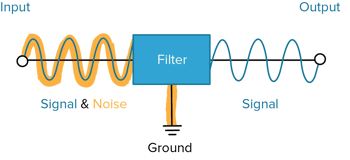
Figure 1. An illustration of the basic concept of how an EMI filter works.
What Applications Need EMI Filters?
EMI filters help ensure reliable operation of power electronic systems by effectively reducing EMI noise and preventing interference with sensitive electronic components which minimizes the risk of malfunction or data corruption, and helps manufacturers meet electromagnetic compatibility standards. EMI filters are commonly used in applications such as power supplies, inverters, motor drives, LED lighting, and other electronic devices where EMI mitigation is critical. With proper EMI filtering, these devices can then be trusted for use in mission-critical applications where failure is not an option such as medical devices and aerospace and defense equipment.
Why are Ceramic Capacitors a Good Fit for EMI Filters?
Ceramic materials possess excellent electrical and mechanical properties that make them suitable for EMI filter applications. Ceramic EMI filters are typically constructed using multilayer ceramic capacitors (MLCCs) or ceramic disc capacitors. These capacitors are designed to have high capacitance values and low equivalent series inductance (ESL) and equivalent series resistance (ESR) to minimize the impedance of the desired power signals. EMI filters made with ceramic are also designed to exhibit high impedance at high frequencies, effectively filtering out the EMI noise.
When ceramic capacitors are used for EMI filters, the filters are typically connected in parallel with the power supply lines or between the power supply and the electronic device being protected. The MLCC used as a filter can be integrated into the printed circuit board (PCB) design or implemented as discrete components. The number and configuration of the filters will depend on the specific EMI requirements and the complexity of the power electronics system.
Helping You Select the Ideal EMI Filtering Option
When an electronic system needs a capacitor to serve a critical role, such as EMI filtering, it is best to consult with expert engineers that can work with you to properly specify the size and type of capacitor needed. As a specialty components manufacturer with unrivaled ceramics expertise, Knowles Precision Devices can help. We make a variety of high-reliability surface and panel mount filters, discoidal capacitors, and planar capacitor arrays that can be used for EMI filtering. Our core wet manufacturing process and ceramic handling expertise allows us to produce components with mechanical precision and electrical accuracy, enabling filter assemblies to function reliably and withstand the most rigorous of electrical specifications.
Checkout our range of EMI filtering options and learn more about our commitment to continue investing in surface-mount EMI filters, even as other manufacturers scale back.
Подавление помех в цепях питания электронных устройств
Помехи, присутствующие в современной электросети, негативно влияют на работу подключённых к ней электронных устройств. Они способны значительно снизить качество работы электроаппаратуры, а в некоторых случаях и привести к её неисправностям.
Значительно уменьшить эти проблемы позволяет правильно спроектированный сетевой фильтр.
Довольно подробное описание компонентов «правильного» сетевого фильтра приведено в статье, опубликованной на станице сайта https://www.433175.ru.
Приведём основные выкладки из статьи:
Для начала рассмотрим типичные виды помех на электросетях:
1. Короткие импульсные помехи, амплитуда которых может в разы превышать номинал питающего напряжения, и возникающие при переключении различных мощных индуктивных нагрузок: контакторов и электродвигателей систем вентиляции, стиральных машин и пр. Длительность – от долей до сотен микросекунд;
2. Шумовые помехи искровой природы от щеточных контактов генераторов тока и нагрузок с вращающимся элементом (амплитуда может достигать десятков вольт при частотном диапазоне до десятков килогерц);
3. Длительные помехи на линейные участки электросети от электроискровых разрядников (дуговая сварка, искрение «плохих» сильноточных контактов промоборудования (частотный диапазон до сотни килогерц);
4. Наводки на линейные участки электросети от радиочастотных излучателей (близкорасположенный вещательный радиоцентр, находящиеся рядом базовые станции сотовой связи). Частотный спектр – от единиц до сотен мегагерц, но размах наводимых на участок электросети сигналов, как правило, невелик.
Скажем, на 10 ампер потребления тока при импульсной помехе до 2 киловольт длительностью до 1мс придется энергия Е= 20А х 2000В х 0,001сек=20Дж. Но поскольку почти одновременно могут наводиться импульсы от переключения нескольких мощных индуктивных нагрузок из великого их множества в электросети, это значение лучше увеличить в несколько раз. Вполне оптимальным значением энергии варистора видится значение порядка 80 Дж.
Оставшуюся ниже напряжения отсечки варистора «бороду» и прочие помехи возможно убрать только электрической фильтрацией. Чтобы не писать много слов, что и как нам еще применить, ограничусь вполне понятными иллюстрациями:
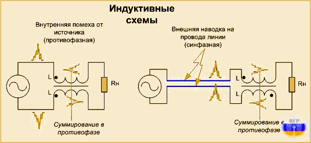
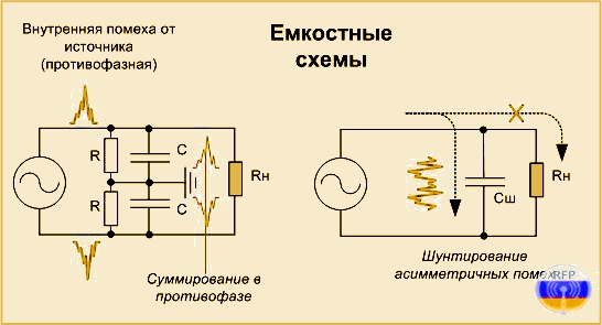
Рис.2 Индуктивные и ёмкостные схемы фильтрации противофазных помех
Ёмкостные схемы более высокочастотны, так как в индуктивных схемах для оптимизации размеров обмоток используют ферриты с высокой магнитной проницаемостью, ограничивающей частоту их применения в несколько десятков или первые сотни килогерц. Причём это должны быть замкнутые магнитопроводы (кольцеобразные или прямоугольные), чтобы не являться переизлучателями помеховых сигналов.
Комбинация перечисленного выше даст нам следующую схему сетевого фильтра:
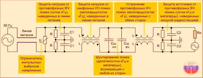
Рис.3 Сетевой фильтр подавления синфазных и противофазных помех
Показанные на приведённой схеме «земли» будут корректно работать только в том случае, если они «местные», т. е. выходят кратчайшим путем напрямую на контур заземления здания, а не тянутся по «наружке» в длинной трехпроводной линии с третьим проводом заземления, лишая схему двухпроводной симметрии.
Ниже указаны типовые номиналы элементов фильтра с несколько большими (для надёжности) величинами рабочих напряжений конденсаторов и мощностей резисторов:
Варистор – Urms= 250В (или Uампл.= 350В)/80. 100 Дж;
R – 300кОм. 1Мом/1. 0,5 Вт;
С1 – 0,015. 0,022мкФ/630В;
L – 1. 5мГн (обмотки примерно до 1,5 мГн с проходным током до 16А можно уместить в один слой на ферритовом кольце проницаемостью 3000 и внешним диаметром 45. 50мм);
Сш нч – 0,22. 0,33мкФ/630В;
Сш вч – 0,01мкФ/630В;
С2 – 4700пФ/630В.
Теперь давайте разберёмся, что такое синфазные и дифференциальные помехи?
Как правило, сетевой фильтр предусматривает наличие трехпроводной сети: фаза, нейтраль и защитное заземление (PE). Помехи, с которыми борется сетевой фильтр, делятся на два вида – синфазные и дифференциальные.
Синфазные помехи – это когда оба провода сети синхронно меняют потенциал относительно земли (PE). Дифференциальные помехи – когда потенциал сетевых проводов разнополярно (в противоположных направлениях) меняется друг относительно друга.
Как можно увидеть на Рис.3, для борьбы с синфазными помехами служит левый синфазный дроссель, состоящий из двух катушек, намотанных на общий сердечник. На самом деле, обозначение начала обмоток синфазных дросселей указывается не так, как приведено на Рис.3, а, в большинстве случаев – как изображено на Рис.4, т. е. с обозначением начала обмоток слева.
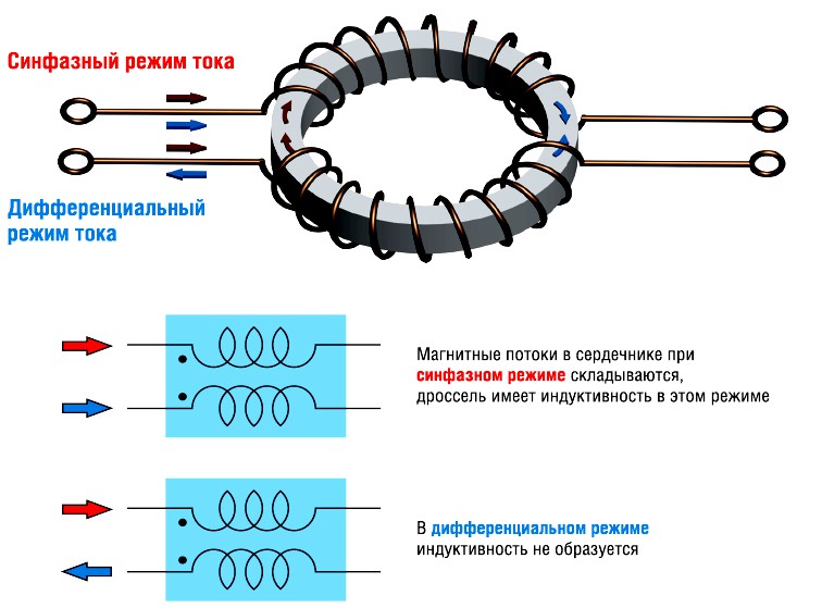
Рис.4 Структура и принцип работы синфазного дросселя
При этом следует иметь в виду, что направление намотки обмоток дросселя – противоположное.
В качестве сердечника чаще всего используется кольцевой магнитопровод с высокой магнитной проницаемостью. Когда через катушки протекают дифференциальные токи, магнитные поля, индуцированные этими токами, взаимно уничтожают друг друга. Если пренебречь омическим сопротивлением катушек, то их входной импеданс в этом случае будет равен нулю. Теоретически они не влияют на прохождение дифференциальных сигналов. В случае появления синфазных токов магнитные потоки обоих катушек складываются, и входной импеданс увеличивается, что приводит к подавлению синфазных токов и значительному снижению амплитуды шумового сигнала.
Благодаря наличию противофазных обмоток, синфазные токи будут генерировать в сердечнике разностный магнитный поток, и сердечник дросселя не будет входить в насыщение даже при наличии очень больших дифференциальных токов. Именно поэтому в синфазных дросселях могут быть использованы сердечники с высокой магнитной проницаемостью без зазора без риска их насыщения и перегрева. Такие дроссели широко выпускаются промышленно.
Совсем другое дело – дроссель для подавления противофазных помех (Рис.3 справа). Здесь обмотки включены синфазно и магнитный поток от них складывается, что создаёт предпосылки для лёгкого насыщения сердечника. Поэтому в данном случае следует использовать либо сердечники с зазором, либо сердечники из распылённого железа, либо два отдельных дросселя с высокими рабочими токами (Рис.5).
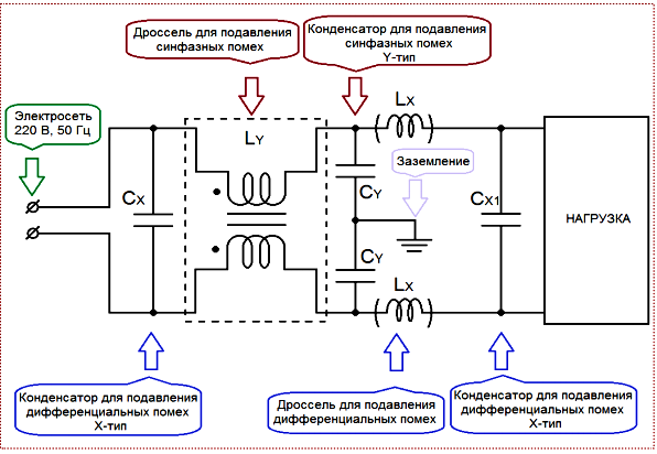
Рис.5 Сетевой фильтр подавления синфазных и дифференциальных помех
Данный фильтр менее эффективен, чем устройство, изображённое на Рис.3, и был приведён лишь для демонстрации исполнения дросселя противофазных помех на двух раздельных сердечниках.
Если к аппаратуре не предъявлять повышенных требований помехо- защищенности, то вполне можно применить и фабричные EMI (RFI) фильтры, предназначенные для уменьшения ВЧ помех и на начальном уровне вполне справляющиеся с возложенными на них обязанностями (Рис.6).
В качестве ориентира можно порекомендовать схему, приведённую на Рис.3. Именно эту схему мы слегка доработаем и разместим в качестве готовой конструкции на следующей странице.
EMI/RFI Filters
Explore the vital role of EMI/RFI filters in electronic circuit design, their types, components, and importance in ensuring device reliability.

Introduction to EMI/RFI Filters
Electromagnetic Interference (EMI) and Radio Frequency Interference (RFI) are significant challenges in electronic circuit design. These phenomena can disrupt proper functioning, degrade performance, and even damage electronic systems. Hence, a critical component called EMI/RFI filters is used to manage and mitigate these issues.
Understanding EMI/RFI
Before we delve into filters, it’s important to understand what EMI and RFI are. EMI is a disturbance generated by an external source that affects an electrical circuit through electromagnetic induction or electrostatic coupling. RFI, a subset of EMI, specifically refers to interference caused by devices emitting radio frequency energy.
EMI/RFI Filters: A Vital Solution
EMI/RFI filters are essential tools designed to prevent or minimize EMI and RFI from entering or exiting electronic devices. These filters are made up of components that absorb or reflect unwanted interference, allowing only the desired signals to pass through. By attenuating the interference, they improve the performance and reliability of electronic systems.
Types of EMI/RFI Filters
- Power Line Filters: These filters reduce EMI from power lines and are typically used in appliances, industrial machinery, and computers.
- Data Line Filters: Data line filters target EMI in data and signal lines, particularly crucial in telecommunications and data transmission.
- RFI Filters: Specifically designed for radio frequency interference, these filters are used in communication and broadcasting devices.
The Importance of EMI/RFI Filters in Circuit Design
The prevalence of electronic devices in our day-to-day lives has increased the potential sources of EMI and RFI. These disturbances can cause malfunctions, data errors, and system failures, severely impacting the reliability and functionality of electronic systems. Consequently, EMI/RFI filters have become an integral part of circuit design, protecting the systems from unwanted disturbances and ensuring optimal performance.
How EMI/RFI Filters Work
At a high level, EMI/RFI filters work by grounding the unwanted signals, which are then dissipated as heat. They do this by using a combination of capacitors and inductors, each addressing different frequency ranges of interference. The capacitors handle high-frequency signals, while the inductors are designed to deal with lower frequency interference.
Key Components of EMI/RFI Filters
- Capacitors: These are passive electronic components that store energy in an electric field. In the context of EMI/RFI filters, capacitors block direct current (DC) while allowing alternating current (AC) to pass, effectively removing the high-frequency interference.
- Inductors: Also known as coils or chokes, inductors are components that store energy in a magnetic field. They are used in EMI/RFI filters to impede changes in current and thereby eliminate low-frequency interference.
Choosing the Right EMI/RFI Filter
Selecting an appropriate EMI/RFI filter is crucial for optimal electronic system performance. Factors to consider include the type and magnitude of the interference, operating frequency, and power requirements of the system, amongst others. Consulting with a professional experienced in electromagnetic compatibility (EMC) can be immensely beneficial in making the right choice.
Regulatory Standards for EMI/RFI
Given the potential damage and disruption that EMI and RFI can cause, regulatory bodies around the world have established standards for electromagnetic compatibility. These standards specify the allowable limits of EMI and RFI emissions from electronic devices, thus ensuring their safe and reliable operation. Compliance with these standards is mandatory for electronic products in many markets, further emphasizing the importance of EMI/RFI filters in circuit design.
Conclusion
EMI/RFI filters play a vital role in modern electronics, ensuring systems function reliably amidst potential electromagnetic and radio frequency interference. With the growing proliferation of electronic devices in our everyday lives, these filters become increasingly crucial. Whether it’s for a simple household appliance or complex industrial machinery, the correct application of EMI/RFI filters can make the difference between a smoothly operating device and one plagued with errors and malfunctions. As technology continues to advance, the design and application of these filters will remain a key focus in electronic circuit design, facilitating the harmonious coexistence of various electronic systems in our interconnected world.
Emi filter что это
EMI filter designs protect sensitive equipment from being damaged by high levels of electrical noise. Almost all electronics contain an EMI filter. It may be embedded into a printed circuit board or used as a separate, standalone device. This includes electronics being used in mission critical, military/defense, secure communications, industrial, medical, and energy platforms. Keep reading to learn more about types of EMI filters and tips on how to choose the right EMI filter.
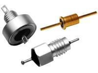
EMI filters function by absorbing the energy that interferes with other electronics in proximity. There are standards in most countries limiting the amount of noise that can emanate from a source. All electronics must follow these regulations in their design.
Find out how to build a Custom EMI Filter Design to satisfy the mechanical, electrical, and power requirements and constraints of a sophisticated OEM design.
What Is EMI?
Electromagnetic interference (EMI) occurs when two or more electrical circuits interfere with each other. This type of disturbance can cause radio frequency (RF) noise, which may disrupt functionality and communication between devices.
EMI can be from intentional or unintentional sources, continuous or intermittent, and at a single frequency or across a broad range of frequencies. EMI encompasses the entire electromagnetic spectrum but is most applicable to modern electronic devices over the frequency range of 10 kHz to 10 GHz.
Key Concepts
- Insertion Loss: reduction of signal power (noise) resulting from the insertion of a device into a circuit (expressed in dB)
- Energy Coupling: transfer of electrical energy from one circuit segment to another
- Energy Storage: capture of energy from a source at one moment in time to be used at a later moment in time
- Signal Conditioning & Electromagnetic Spectrum Management: EMI protection products manage the signal and energy that exist in 50Hz to 10GHz range of the electromagnetic spectrum
Why Do We Need To Have EMI Filters?
EMI filter designs provide energy efficiency, and power management, addressing both conducted and radiated EMI for aircraft, rugged and unmanned vehicles, power supplies, automation equipment, and diagnostic imaging. And yes, there are also EMI filters in that smartphone in your pocket and the smartwatch on your wrist.
EMI filtering components and assemblies also provide solutions for Electromagnetic Compatibility (EMC). EMC are the laws and regulations of the country where the products are being distributed. All electronic and electromechanical products must conform to EMC compliance.
Engineers should always seek to reduce the levels of interference in their electronic products during the design phase. Often, it’s during the EMC testing phase when the amount of EMI is discovered.

What Are The Different Types Of EMI Filters?
There are many EMI filters available. They come in two major categories–active and passive.
Active filters use an internal power supply to generate electricity. Active EMI filters work by detecting the voltage at the input and generating a current flow in the opposite direction. This effectively removes the EMI current causing a disturbance. This technique makes use of the active electronic elements and applies an internal circuit to block out unwanted frequencies. By looking at EMI filter requirements, design engineers will achieve a reduction in size, cost, and improved performance.
Passive filters absorb unwanted energy. Passive EMI filters reduce emissions of a power electronic circuit and are constructed from only passive components: capacitors, resistors, transformers, and inductors. These elements are fine tuned to produce electrical resonance at a single frequency, or through a band of frequencies. Passive EMI filters will suppress harmonic currents and decrease voltage distortion in sensitive elements of electronic systems.
Which Type Of EMI Filter Is Best For My Design?
There are several benefits to using a passive EMI filter over an active EMI filter, including the strength of its internal elements. They are better for large signals common in modern electronics, are often more economical, and power supplies are unnecessary.