Overview
Routing is the process of selecting paths across the networks to move packets from one host to another.
How Routing Works
Let’s look at a basic configuration example to illustrate how routing is used to forward packets between two local networks and to the Internet.
In this setup, we have several networks:
- two client networks (192.168.2.0/24 and 192.168.1.0/24);
- one network to connect routers (172.16.1.0/30), usually called backbone;
- the last network (10.1.1.0/24) connects our gateway router (Router1) to the internet.
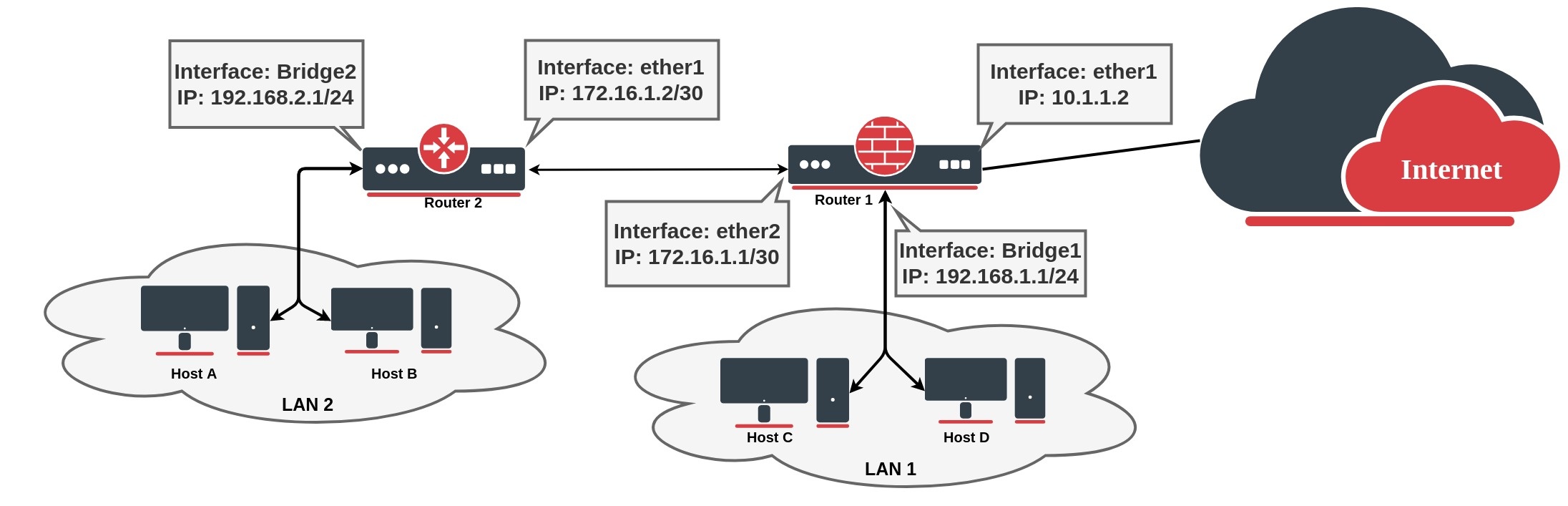
/ip address add address=172.16.1.2/30 interface=ether1 add address=192.168.2.1/24 interface=bridge2
Router1 (gateway) where ether1 connects to the internet:
/ip address add address=10.1.1.2/24 interface=ether1 add address=172.16.1.1/30 interface=ether2 add address=192.168.1.1/24 interface=bridge1
If we look, for example, at the Router1 routing table, we can see that the router knows only about directly connected networks. At this point, when the Client from LAN1 tries to reach the client from LAN2 (192.168.2.0/24), a packet will be dropped on the router, because the destination is unknown for the particular router:
[admin@MikroTik] > /ip/route> print Flags: D - dynamic; X - disabled, I - inactive, A - active; C - connect, S - static, r - ri p, b - bgp, o - ospf, d - dhcp, v - vpn Columns: DST-ADDRESS, GATEWAY, Distance DST-ADDRESS GATEWAY D DAC 10.1.1.0/24 ether1 0 DAC 172.16.1.0/30 ether2 0 DAC 192.168.1.0/24 bridge1 0
To fix this we need to add a route that tells the router what is the next device in the network to reach the destination. In our example next hop is Router2, so we need to add a route with the gateway that points to the Routers 2 connected address. This type of route is known as a static route:
[admin@MikroTik] > /ip route add dst-address=192.168.2.0/24 gateway=172.16.1.2 [admin@MikroTik] > /ip/route> print Flags: D - dynamic; X - disabled, I - inactive, A - active; C - connect, S - static, r - ri p, b - bgp, o - ospf, d - dhcp, v - vpn Columns: DST-ADDRESS, GATEWAY, Distance DST-ADDRESS GATEWAY D DAC 10.1.1.0/24 ether1 0 DAC 172.16.1.0/30 ether2 0 DAC 192.168.1.0/24 bridge1 0 0 AS 192.168.2.0/24 172.16.1.2
At this point packet from LAN1 will be successfully forwarded to LAN2, but we are not over yet. Router2 does not know how to reach LAN1, so any packet from LAN2 will be dropped on Router2.
If we look again at the network diagram, we can clearly see that Router2 has only one point of exit. It is safe to assume that all other unknown networks should be reached over the link to Router1. The easiest way to do this is by adding a default route: To add a default route set destination 0.0.0.0/0 or leave it blank:
/ip route add gateway=172.16.1.1
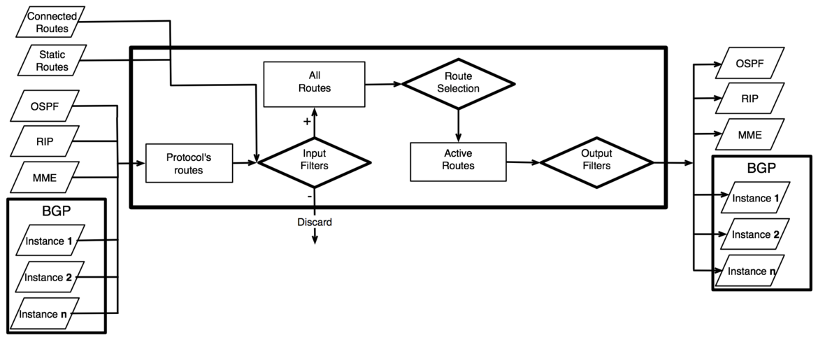
As we have seen from the example setup, there are different groups of routes, based on their origin and properties.
Routing Information
RouterOS routing information consists of two main parts:
- FIB (Forwarding Information Base), is used to make packet forwarding decisions. It contains a copy of the necessary routing information.
- RIB (Routing Information Base) contains all learned prefixes from routing protocols (connected, static, BGP, RIP, OSPF).

Routing Information Base
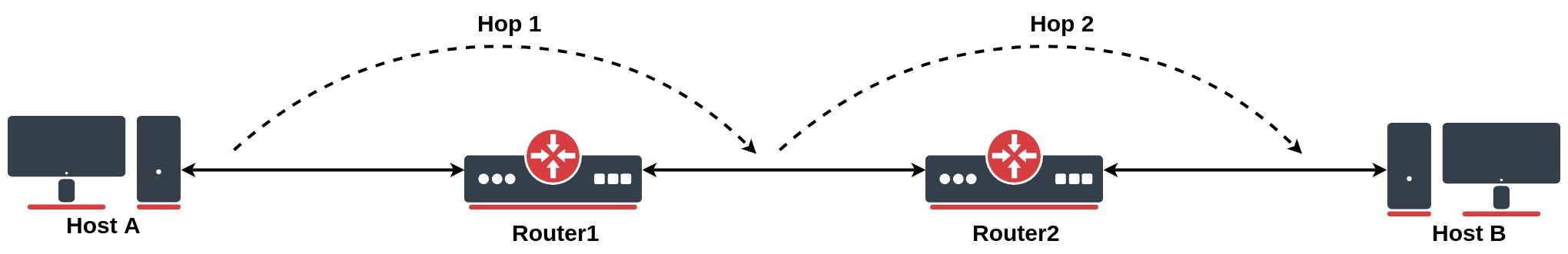
Routing Information Base is a database that lists entries for particular network destinations and their gateways (address of the next device along the path or simply next-hop). One such entry in the routing table is called route.
A hop occurs when a packet is passed from one network segment to another.
By default, all routes are organized in one «main» routing table. It is possible to make more than one routing table which we will discuss further in this article, but for now, for sake of simplicity, we will consider that there is only one «main» routing table.
RIB table contains complete routing information, including static routes and policy routing rules configured by the user, routing information learned from dynamic routing protocols (RIP, OSPF, BGP), and information about connected networks.
Its purpose is not just to store routes, but also to filter routing information to calculate the best route for each destination prefix, to build and update the Forwarding Information Base, and distribute routes between different routing protocols.
Connected Routes
Connected routes represent the network on which hosts can be directly reached (direct attachment to Layer2 broadcast domain). These routes are created automatically for each IP network that has at least one enabled interface attached to it (as specified in the /ip address or /ipv6 address configuration). RIB tracks the status of connected routes but does not modify them. For each connected route there is one IP address item such that:
- address part of the dst-address of the connected route is equal to a network of IP address item.
- netmask part of dst-address of the connected route is equal to the netmask part of the address of the IP address item.
- gateway of the connected route is equal to the actual-interface of the IP address item (same as an interface, except for bridge interface ports) and represents an interface where directly connected hosts from the articular Layer3 network can be reached.
The preferred source is not used anymore for connected routes. FIB chooses the source address based on the out-interface. This allows making setups that in ROS v6 and older were considered invalid. See examples for more details.
Default Route
A default route is used when the destination cannot be resolved by any other route in the routing table. In RouterOS dst-address of default route is 0.0.0.0/0 (for IPv4) and ::/0 (for IPv6) routes. If the routing table contains an active default route, then the routing table lookup in this table will never fail.
Typically home router routing table contains only connected networks and one default route to forward all outgoing traffic to ISP’s gateway:
[admin@TempTest] /ip/route> print Flags: D - dynamic; X - disabled, I - inactive, A - active; C - connect, S - static, r - ri p, b - bgp, o - ospf, d - dhcp, v - vpn Columns: DST-ADDRESS, GATEWAY, Distance # DST-ADDRESS GATEWAY D DAd 0.0.0.0/0 10.155.125.1 1 DAC 10.155.125.0/24 ether12 0 DAC 192.168.1.0/24 vlan2 0
Hardware Offloaded Route
Devices with Layer 3 Hardware Offloading ( L3HW , otherwise known as IP switching or HW routing) allows to offload packet routing onto the switch chip. When L3HW is enabled, such routes will display H-flag:
[admin@MikroTik] > /ip/route print where static Flags: A - ACTIVE; s - STATIC, y - COPY; H - HW-OFFLOADED Columns: DST-ADDRESS, GATEWAY, DISTANCE # DST-ADDRESS GATEWAY D 0 AsH 0.0.0.0/0 172.16.2.1 1 1 AsH 10.0.0.0/8 10.155.121.254 1 2 AsH 192.168.3.0/24 172.16.2.1 1
By default, all the routes are participating to be hardware candidate routes. To further fine-tune which traffic to offload, there is an option for each IP or IPv6 static route to disable/enable suppress-hw-offload .
For example, if we know that majority of traffic flows to the network where servers are located, we can enable offloading only to that specific destination:
/ip route set [find where static && dst-address!="192.168.3.0/24"] suppress-hw-offload=yes
Now only the route to 192.168.3.0/24 has H-flag, indicating that it will be the only one eligible to be selected for HW offloading:
[admin@MikroTik] > /ip/route print where static Flags: A - ACTIVE; s - STATIC, y - COPY; H - HW-OFFLOADED Columns: DST-ADDRESS, GATEWAY, DISTANCE # DST-ADDRESS GATEWAY D 0 As 0.0.0.0/0 172.16.2.1 1 1 As 10.0.0.0/8 10.155.121.254 1 2 AsH 192.168.3.0/24 172.16.2.1 1
H-flag does not indicate that route is actually HW offloaded, it indicates only that route can be selected to be HW offloaded.
Multipath (ECMP) routes
To implement some setups, such as load balancing, it might be necessary to use more than one path to a given destination.
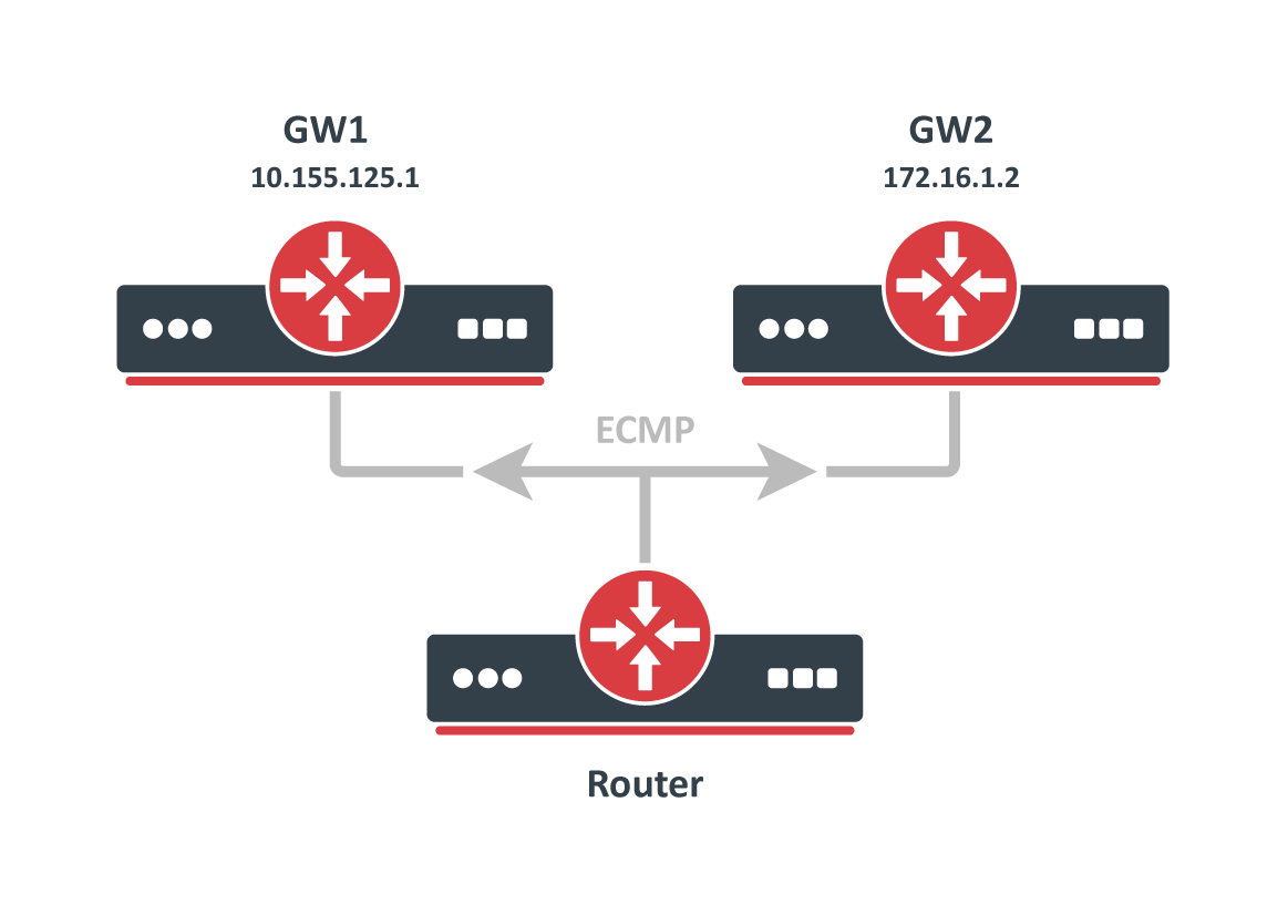
ECMP (Equal cost multi-path) routes have multiple gateways (next-hop) values. All reachable next-hops are copied to FIB and are used to forward packets.
These routes can be created manually, as well as dynamically by any of the dynamic routing protocols (OSPF, BGP, RIP). Multiple equally preferred routes to the same destination will have assigned + flag and grouped together automatically by RouterOS (see example below).
[admin@TempTest] /ip/route> print Flags: D - DYNAMIC; I - INACTIVE, A - ACTIVE; C - CONNECT, S - STATIC, m - MODEM; + - ECMP Columns: DST-ADDRESS, GATEWAY, DISTANCE # DST-ADDRESS GATEWAY D 0 AS+ 192.168.2.0/24 10.155.125.1 1 1 AS+ 192.168.2.0/24 172.16.1.2 1
Route Selection
There can be multiple routes with the same destination received from various routing protocols and from static configurations but only one (best) destination can be used for packet forwarding. To determine the best path, RIB runs a Route Selection algorithm which picks the best route from all candidate routes per destination.
Only routes that meet the following criteria can participate in the route selection process:
- Route is not disabled.
- If the type of route is unicast it must have at least one reachable next-hop. ( if a gateway is from connected network and there is connected route active, the gateway is considered as reachable)
- Route should not be synthetic.
The candidate route with the lowest distance becomes an active route. If there is more than one candidate route with the same distance, the selection of the active route is arbitrary.
Nexthop Lookup
Nexthop lookup is a part of the route selection process. Its main purpose is to find a directly reachable gateway address (next-hop). Only after a valid next-hop is selected router knows which interface to use for packet forwarding.
Nexthop lookup becomes more complicated if routes have a gateway address that is several hops away from this router (e.g. iBGP, multihop eBGP). Such routes are installed in the FIB after the next-hop selection algorithm determines the address of the directly reachable gateway (immediate next-hop).
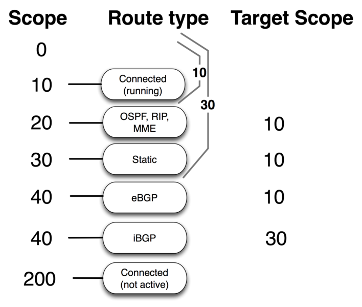
It is necessary to restrict the set of routes that can be used to look up immediate next-hops. Nexthop values of RIP or OSPF routes, for example, are supposed to be directly reachable and should be looked up only using connected routes. This is achieved using scope and target-scope properties.
Routes with a scope greater than the maximum accepted value are not used for next-hop lookup. Each route specifies the maximum accepted scope value for its nexthop in the target-scope property. The default value of this property allows nexthop lookup only through connected routes, with the exception of iBGP routes that have a larger default value and can lookup nexthop also through IGP and static routes.
There are changes in RouterOS v7 nexthop lookup.
Routes are processed in scope order, and updates to routes with a larger scope cannot affect the state of nexthop lookup for routes with a smaller scope.
Consider an example from v6:
/ip route add dst-address=10.0.1.0/24 gateway=10.0.0.1 scope=50 target-scope=30 comment=A /ip route add dst-address=10.0.2.0/24 gateway=10.0.0.1 scope=30 target-scope=20 comment=B /ip route add dst-address=10.0.0.0/24 scope=20 gateway=WHATEVER comment=C
Gateway 10.0.0.1 is recursively resolved through C using the smallest referring scope (scope 20 from route B), both routes are active. Now we change both A and B at the same time:
/ip route set A target-scope=10
Suddenly, applying an update to route A makes the gateway of route B inactive. This is because in v6 there is only one gateway object per address.
v7 keeps multiple gateway objects per address, one for each combination of scope and gateway check.
When target-scope or gateway check of a route is changed, ROS v7 will not affect other routes, as it does in v6. In v7 target-scope and gateway check are properties that are internally attached to the gateway, not to the route.
Gateway check can be extended by setting check-gateway parameter. Gateway reachability can be checked by sending ARP probes, or ICMP messages or by checking active BFD sessions. The router periodically (every 10 seconds) checks gateway by sending either ICMP echo request (ping) or ARP request (arp). If no response from gateway is received for 10 seconds, request times out. After two timeouts gateway is considered unreachable. After receiving reply from gateway it is considered reachable and timeout counter is reset.
Route Storage
Routing information is stored to take as little memory as possible in a common case. These optimizations have non-obvious worst cases and impact on performance.
All routes and gateways are kept in a single hierarchy by the prefix/address.
Dst [4]/0 1/0+4 18Each of these 'Dst' corresponds to a unique 'dst-address' of route or address of the gateway. Each 'Dst' requires one or more 'T2Node' objects as well.
All routes with the same 'dst-address' are kept in Dst in a list sorted by route preference.
Note: WORST CASE: having a lot of routes with the same 'dst-address' is really slow! even if they are inactive! because updating a sorted list with tens of thousands of elements is slow!Route order changes only when route attributes change. If the route becomes active/inactive, the order does not change.
Each Route has three copies of route attributes:
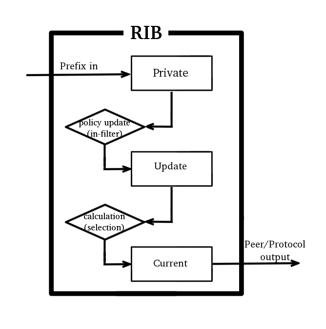
- private -- what is received from the peer, before passing in-filters.
- updated -- what is the result of applying in-filters.
- current -- what are the attributes currently used by the route.
Periodically (when needed), update attributes are calculated from private attributes. This happens when route update is received, or when in-filter is updated.
When the routing table is recalculated, current attributes are set to the value from updated attributes.
This means, that usually if there is no in-filter that changes route attributes, private, updated, and current share the same value.
Route attributes are kept in several groups:
- L1 Data - all flags, list of extra properties, as-path;
- L2 Data - nexthops, RIP,OSPF,BGP metrics, route tags, originators etc.
- L3 Data - distance, scope, kernel type, MPLS stuff
- extra properties - communities, originator, aggregator-id, cluster-list, unknown
Having for example many different combinations of distance and scope route attributes will use more memory!
Matching communities or as-path using regexp will cache the result, to speed up filtering. Each as-path or community value has a cache for all regexp, which is filled on-demand with match results.
Note: WORST CASE: changing attributes in 'in-filter' will make the route program use more memory! Because 'private' and 'updated' attributes will be different! Having a lot of different regexps will make matching slow and use a lot of memory! Because each value will have a cache with thousands of entries!
Detailed info about used memory by routing protocols can be seen in /routing stats memory menu
Forwarding Information Base
FIB (Forwarding Information Base) contains a copy of the information that is necessary for packet forwarding:
- all active routes
- policy routing rules
Each route has dst-address property, that specifies all destination addresses this route can be used for. If there are several routes that apply to a particular IP address, the most specific one (with the largest netmask) is used. This operation (finding the most specific route that matches the given address) is called ''routing table lookup''.
Only one Best route can be used for packet forwarding. In cases where the routing table contains several routes with the same dst-address, all equally best routes are combined into one ECMP route. The best route is installed into FIB and marked as ''active''.
When forwarding decision uses additional information, such as the source address of the packet, it is called policy routing. Policy routing is implemented as a list of policy routing rules, that select different routing tables based on destination address, source address, source interface, and routing mark (can be changed by firewall mangle rules) of the packet.
Routing table lookup
FIB uses the following information from the packet to determine its destination:
- source address
- destination address
- source interface
- routing mark
Possible routing decisions are:
- receive packet locally
- discard the packet (either silently or by sending an ICMP message to the sender of the packet)
- send the packet to a specific IP address on a specific interface
Run routing decision:
- check that packet has to be locally delivered (the destination address is the address of the router)
- process implicit policy routing rules
- process policy routing rules added by a user
- process implicit catch-all rule that looks up destination in the ''main'' routing table
- the returned result is "network unreachable"
The result of the routing decision can be:
- IP address of nexthop + interface
- point-to-point interface
- local delivery
- discard
- ICMP prohibited
- ICMP host unreachable
- ICMP network unreachable
Rules that do not match the current packet are ignored. If a rule has action:
- drop or unreachable, then it is returned as a result of the routing decision process.
- lookup then the destination address of the packet is looked up in the routing table that is specified in the rule. If the lookup fails (there is no route that matches the destination address of the packet), then FIB proceeds to the next rule.
- lookup-only similar to lookup except that lookup fails if none of the routes in the table matches the packet.
- if the type of the route is blackhole, prohibit, or unreachable, then return this action as the routing decision result;
- if this is a connected route or route with an interface as the gateway value, then return this interface and the destination address of the packet as the routing decision result;
- if this route has an IP address as the value of gateway, then return this address and associated interface as the routing decision result;
- if this route has multiple values of nexthop, then pick one of them in round-robin fashion.
Show Routes
In RouterOS you have three menus to see the current state of routes in the routing table:
- /ip route - list IPv4 routes and basic properties
- / ipv6 route - list IPv6 routes and basic properties
- / routing route - list all routes with extended properties
/ routing route menu currently is read-only. To add or remove routes / ip ( ipv6 ) route menus should be used.
Example output
[admin@MikroTik] /ip/route> print Flags: D - dynamic; X - disabled, I - inactive, A - active; C - connect, S - stati c, r - rip, b - bgp, o - ospf, d - dhcp, v - vpn Columns: DST-ADDRESS, GATEWAY, DIstance # DST-ADDRESS GATEWAY DI 0 XS 10.155.101.0/24 1.1.1.10 1 XS 11.11.11.10 D d 0.0.0.0/0 10.155.101.1 10 2 AS 0.0.0.0/0 10.155.101.1 1 3 AS + 1.1.1.0/24 10.155.101.1 10 4 AS + 1.1.1.0/24 10.155.101.2 10 5 AS 8.8.8.8 2.2.2.2 1 DAC 10.155.101.0/24 ether12 0 | ||| | | | | | ||| | | | \----Distance | ||| | | \--Configured gateway | ||| | \-- dst prefix | ||| \----- ECMP flag | ||\------- protocol flag (bgp, osf,static,connected etc.) | |\-------- route status flag (active, inactive, disabled) | \--------- shows if route is dynamic \----------- console order number (shown only for static editable routes)
routing route output is very similar to ip route except that it shows routes from all address families in one menu and lists filtered routes as well.
[admin@MikroTik] /routing/route> print Flags: X - disabled, I - inactive, F - filtered, U - unreachable, A - active; c - connect, s - static, r - rip, b - bgp, o - ospf, d - dhcp, v - vpn, a - ldp-address, l - ldp-mapping Columns: DST-ADDRESS, GATEWAY, DIStance, SCOpe, TARget-scope, IMMEDIATE-GW DST-ADDRESS GATEWAY DIS SCO TAR IMMEDIATE-GW Xs 10.155.101.0/24 Xs d 0.0.0.0/0 10.155.101.1 10 30 10 10.155.101.1%ether12 As 0.0.0.0/0 10.155.101.1 1 30 10 10.155.101.1%ether12 As 1.1.1.0/24 10.155.101.1 10 30 10 10.155.101.1%ether12 As 8.8.8.8 2.2.2.2 1 254 254 10.155.101.1%ether12 Ac 10.155.101.0/24 ether12 0 10 ether12 Ic 2001:db8:2::/64 ether2 0 10 Io 2001:db8:3::/64 ether12 110 20 10 Ic fe80::%ether2/64 ether2 0 10 Ac fe80::%ether12/64 ether12 0 10 ether12 Ac fe80::%bridge-main/64 bridge-main 0 10 bridge-main A ether12 0 250 A bridge-main 0 250
routing route print detail shows more advanced info useful for debugging
[admin@MikroTik] /routing route> print detail Flags: X - disabled, I - inactive, F - filtered, U - unreachable, A - active; c - connect, s - static, r - rip, b - bgp, o - ospf, d - dhcp, v - vpn, a - ldp-address, l - ldp-ma> + - ecmp Xs dst-address=10.155.101.0/24 Xs d afi=ip4 contribution=best-candidate dst-address=0.0.0.0/0 gateway=10.155.101.1 immediate-gw=10.155.101.1%ether12 distance=10 scope=30 target-scope=10 belongs-to="DHCP route" mpls.in-label=0 .out-label=0 debug.fwp-ptr=0x201C2000 As afi=ip4 contribution=active dst-address=0.0.0.0/0 gateway=10.155.101.1 immediate-gw=10.155.101.1%ether12 distance=1 scope=30 target-scope=10 belongs-to="Static route" mpls.in-label=0 .out-label=0 debug.fwp-ptr=0x201C2000
- Нет меток
Инструкции по настройке MikroTik

Когда нужно применять статическую маршрутизацию в MikroTik
Любая корпоративная сеть, как правило состоит из многоуровневой коммутации как на уровне самого роутера, так и во внешних сервисах. В качестве примера будет сформирован список случаев, когда актуально обратиться к настройке статического маршрута(route) на маршрутизаторе(роутере) MikroTik:
- При добавлении статического адреса на какой-либо интерфейс. Это может быть как интернет соединение(ppoe, dhcp client, static address), так и обычная локальная настройка интерфейса в MikroTik.
- Для обмена данным связки L2TP\PPTP VPN сервера и узлами, которые находятся ЗА VPN клиентом. Эта частая связка, когда в качестве VPN клиента выступает не конечный узел, а установлен маршрутизатор(роутер), за которым может быть множество узлов(при объединении двух офисов).
- При использовании нескольких провайдеров и создании различных правил по балансировки нагрузке или автопереключению(резервированию) интернета.
- Когда нужно разделить узлы локальной сети на группы, каждая их которых будет использовать разные правила для выхода в интернет.
- Индивидуальные случаи, когда нужно задать предопределенное правило движение трафика для узла, которое не создаётся автоматически.
Нужно настроить статическую маршрутизацию MikroTik?
Мы поможем настроить: маршрутизатор(роутер), точку доступа или коммутатор.
Как настроить “static routing” в MikroTik
Будет рассмотрена запись статического маршрута, с детальным описанием рабочих параметров.
Настройка находится IP→Routes
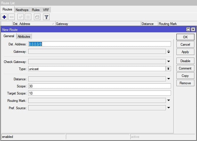
Dst. Address – конечный адресат, популярные значения
- 0.0.0.0/0 – интернет;
- 192.168.0.0/24 – подсеть;
- 192.168.0.50 – конечный узёл;
Gateway – шлюз, которому будет отправлен пакет.
Check Gateway – проверка доступности шлюза:
- arp – по наличию записи в таблице ARP;
- ping – посредством отправки icmp запросов.
Этот пункт позволяет произвести точное определение не доступности шлюза и является рекомендованным, при использовании автоматического переключения линии интернета.
Type – маршруты, которые не указывают nexthop для пакетов, но вместо этого выполняют некоторые другие действия с пакетами, имеют тип, отличный от обычного unicast(одноадресного). Маршрут blackhole(черная дыра) молча отбрасывает пакеты, в то время как маршруты, unreachable(недоступные) и prohibit(запрещающие), отправляют сообщение ICMP Destination Unreachable (код 1 и 13 соответственно) на адрес источника пакета.
Distance – определение приоритета заданного маршрута. Чем ниже число, те выше приоритет.
Scope\Target Scope – параметры рекурсивной маршрутизации, состоящей из этапов:
- Маршрут ищет интерфейс для отправки пакета исходя из своего значения scope и всех записей в таблице main с меньшими или равными значениями target scope
- Из найденных интерфейсов выбирается тот, через который можно отправить пакет указанному шлюзу
- Интерфейс найденной connected записи выбирается для отправки пакета на шлюз
Больше информации по использованию параметров ааа можно найти в соответствующем руководстве “Manual:Using scope and target-scope attributes → ”
Routing Mark – направлять пакеты из заданной таблицы маршрутизации. Как правило этот параметр или пустой или заполняется промаркерованнымb маршрутами из раздела Mangle.
Pref. Source – задается IP адрес, от которого будет отправлен пакет. Этот параметр актуален, когда на интерфейсе несколько IP адресов.
Примеры статических маршрутов в MikroTik
Настройка статического маршрута с предварительной маркировкой пакета(раздел Mangle)
Применяется для использования разных линий интернета для разных узлов. К примеру в сети расположено два сервера, использующие внешние порты 80 и 443.
Для работы правила нужно промаркировать трафик(раздел Mangle) и указать его в параметре Routing Mark.
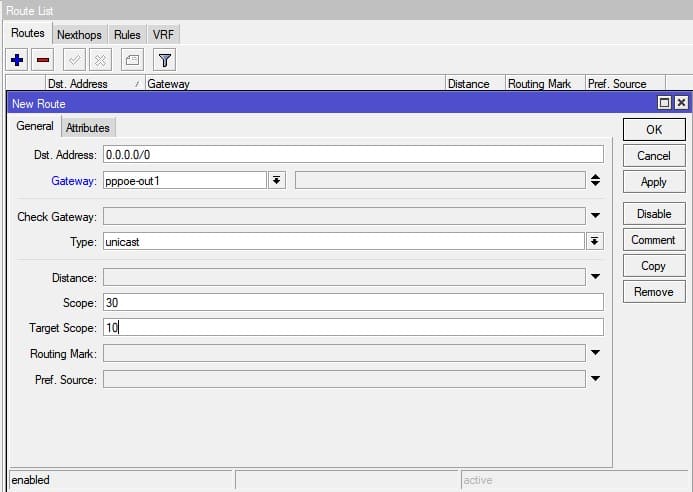
Ручное добавление статического маршрута для PPPOE подключения
Применяется, когда нужно изменить некоторые параметры в автоматическом добавлении маршрута(Add default route)
Настройка резервного интернет канала
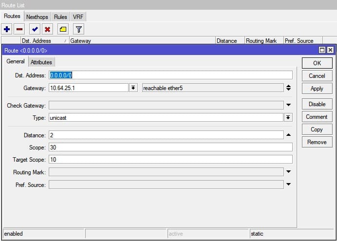
В качестве параметра переключателя между провайдера используется параметр Distance. Трафик в этом случае направляется в тот маршрут, значение Distance которого МЕНЬШЕ,
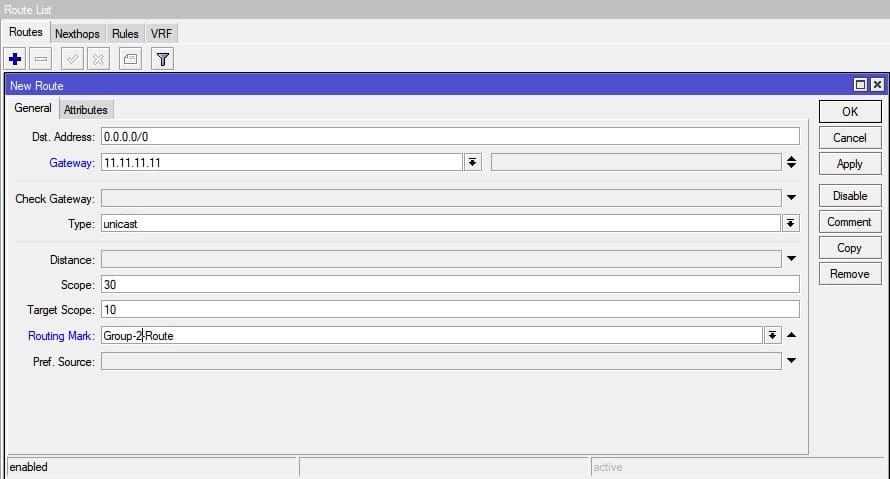
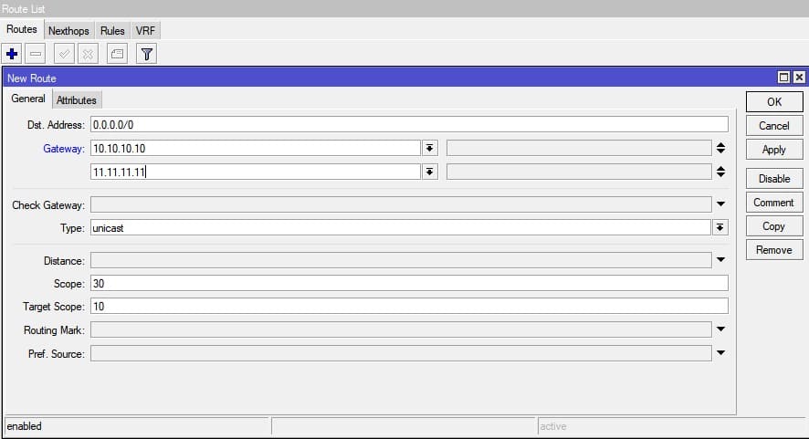
Балансировка нагрузки для двух интернет каналов
Осуществляется через почередное указание шлюзов провайдера. Параметром Gateway можно задавать не только последовательность, но и управлять количественной частью. К примеру, если вам нужно чтобы к провайдеру со шлюзом 11.11.11.11 уходило в 2 раза больше трафика(или там канал в 2 раза быстрее) достаточно этот шлюз указать два раза.
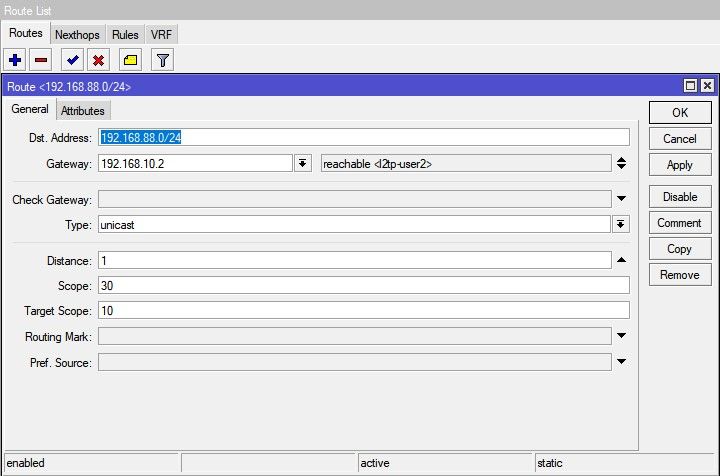
Добавление статического маршрута для VPN соединения
В качестве шлюза указывается IP адрес VPN клиента. Использование таких маршрутов в MikroTik популярно, когда в качестве L2TP или PPTP VPN клиента выступает роутер, со своей подсетью.
Есть вопросы или предложения по настройке статической маршрутизации в MikroTik? Активно предлагай свой вариант настройки! Оставить комментарий →
Настройка маршрутизатора MikroTik с нуля (RouterOS 7). [Часть 1]
Продолжаем рублику « Микротик для чайников » . В данной статье рассматривается пошаговая настройка маршрутизаторов MikroTik с установленной RouterOS 7 для дома и небольшого офиса с нуля. Обычно такая настройка включает в себя настройку работы в локальной сети, настройку Wi-Fi, настройку Firewall, настройку доступа в сеть интернет и настройки безопасности устройства.
Так как объем материала получается достаточно большим, то статья будет разбита на две части, в первой части будет изложен материал по настройке локальной сети, минимально необходимая настройка Firewall и подключение к сети интернет. Этого вполне достаточно чтобы устройства, подключенные проводом, имели доступ в интернет.
Если у вас уже есть настроенное устройство с версией RouterOS 6, и вы собираетесь обновиться до 7 версии, то настраивать с нуля его нет необходимости, обновление обычно происходит без каких-либо проблем.
Описанные в статье настройки производились на RouteOS версии 7.6, т.к. данная операционная система едина для всех маршрутизаторов компании MikroTik, то на каком устройстве будет производится настройка не имеет абсолютно никакого значения, различия в устройствах обычно только в установленном железе и количестве портов.
- Подготовка к настройке
- Подключение к MikroTik и сброс текущей конфигурации
- Настройка локальной сети
- Создание Bridge
- Назначение IP адреса интерфейсу Bridge
- Настройка DHCP сервера
- Добавление правил
- Настройка NAT
- Изменение MAC адреса (Clone MAC)
- Получение IP адреса по DHCP интерфейсу WAN
- Назначение IP адреса интерфейсу WAN вручную
- Настройка маршрута по умолчанию
Подготовка к настройке
Скачиваем последнюю версию WinBox с сайта MikroTik, (прямые ссылки для версии WinBox_x32 и WinBox_x64), RouterOS версии 7.6 требует версию WinBox не ниже 3.37.
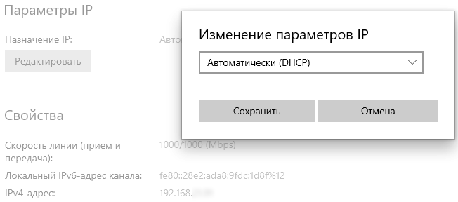
В настройках сетевой карты компьютера выставляем получение IPv4 адреса по DHCP. В Windows 10 это можно сделать двумя способами:
Способ 1. Пуск -> Параметры -> Сеть и Интернет -> Свойства (Ethernet) -> Редактировать (Параметры IP) . Изменение параметров IP -> Автоматически (DHCP) .
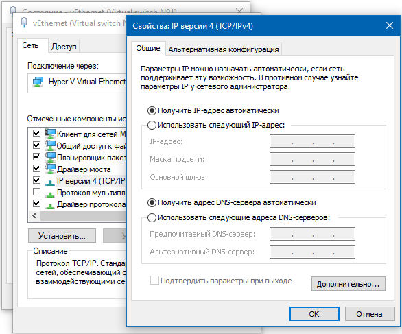
Способ 2. Пуск -> Служебные - Windows -> Панель управления -> Все элементы панели управления -> Центр управления сетями и общим доступом -> Изменение параметров адаптера -> правой клавишей на Подключение по локальной сети -> Свойства -> IP версии 4 (TCP/IP) -> Свойства , выбрать Получить IP-адрес автоматически и Получить адрес DNS сервера автоматически .
Включаем MikroTik и подключаем его патч-кордом к компьютеру, в какой порт на MikroTik особого значения не имеет, но на устройствах с настройками по умолчанию, обычно, первый порт настроен на подключение к провайдеру, остальные собраны в Bridge для подключения устройств локальной сети, поэтому лучше выбрать Ethernet порт отличный от первого.
ВНИМАНИЕ! Провод провайдера в MikroTik не подключать! Это будет сделано позднее.
Подключение к MikroTik и сброс текущей конфигурации
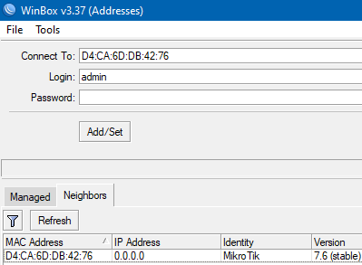
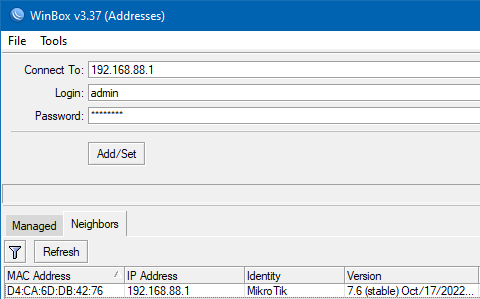
Запускаем WinBox, на вкладке Neighbors должно отобразиться найденное устройство. Подключиться можно либо по MAC адресу, либо по IP адресу, для удобства, чтобы не набирать руками можно нажать на соответствующее поле.
Если в поле IP адрес указано 0.0.0.0 , это означает что данный порт или устройство не настроены должным образом, в таком случае подключаемся по MAC адресу. По умолчанию пользователь (Login): admin , пароль отсутствует.
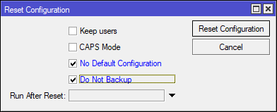
Делаем полный сброс конфигурации, переходим System -> Reset Configuration , в открывшемся окне выбираем No Default Configuration и Do Not Backup , нажимаем кнопку Reset Configuration . Здесь пункт No Default Configuration - не загружать заводские настройки по умолчанию, получаем полностью ненастроенное устройство. Пункт Do Not Backup - перед сбросом не делать резервную копию устройства, если устройство ранее было настроено и данные настройки Вам дороги как светлая память о прошлом, то данный пункт можно не выбирать.
Настройка локальной сети
После сброса подключаемся программой WinBox к устройству по MAC адресу, здесь уже без вариантов, т.к. настроенных адресов у устройства больше нет. По умолчанию пользователь (Login): admin , пароль отсутствует.
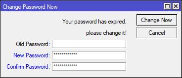
При первом входе в целях безопасности будет предложено установить новый пароль пользователю admin . Придумываем, запоминаем, заполняем, нажимаем Change Now .
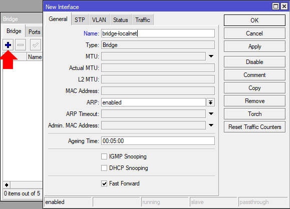
Создаем Bridge интерфейс, в котором будут объединены Ethernet порты и Wlan интерфейсы локальной сети, по сути создаем Switch работающий в локальной сети. Выбираем Bridge , в открывшемся окне на вкладке Bridge нажимаем + . В окне создания нового интерфейса в поле Name вводим удобное для понимая в дальнейшем наименование и нажимаем OK .
Добавляем в созданный Bridge интерфейс порты, к которым будут подключаться компьютеры и устройства, работающие в локальной сети.
Небольшое отступление для тех, кто не понимает, что мы делаем, остальные смело листают к следующему абзацу. В 99% домашних роутерах, будь то D-Link, Tp-Link, Asus или Xiaomi уже всё сделано производителем из коробки и изменить это нельзя. Один порт сделан для подключения к провайдеру, он подписан WAN и, скорее всего выделен отдельным цветом, остальные порты (как правило их четыре) и модули беспроводной связи объединены в один Switch, а точнее в Bridge интерфейс, которому назначен адрес что-то из 192.168.1.1. В MikroTik так реализовано в конфигурации по умолчанию, порт с цифрой 1 предназначен для подключения к провайдеру, порты 2 - 5 и Wlan объединены в один Bridge. Но MikroTik и прекрасен тем, что конфигурацию можно настроить под себя, например, порт 1 задействовать под основного провайдера, порт 2 под резервного провайдера, порт 3 и 4 объединить в один Bridge для локальной сети где будут домашние компьютеры, а порты 4 и 5 (6, 7, 8 столько, сколько есть на устройстве) объединены в Bridge где будут подключены устройства умного дома. При этом ограничить доступ к сети IoT устройств из локальной сети или сделать чтобы IoT устройства ходили в интернет через второго провайдера. Здесь мы не будем рассматривать сложные конфигурации и ограничимся самой обычной, на уровне домашнего маршрутизатора из поднебесной.
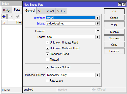
Итак, на вкладке Ports добавляем Ethernet интерфейсы в созданный Bridge. Нажимаем + , в открывшемся окне в поле Interface выбираем нужный интерфейс, в поле Bridge выбираем созданный Bridge интерфейс, нажимаем OK . Повторяем пока не добавим все необходимые интерфейсы. Не забываем добавить порт, к которому подключен наш компьютер.
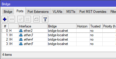
После добавления всех необходимых портов должен быть примерно такой список:
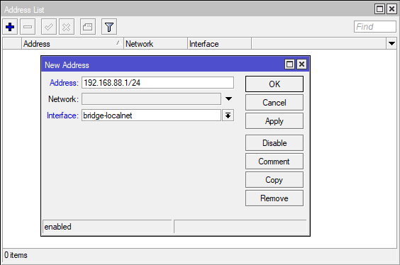
Переходим к настройке IP адреса устройства в локальной сети. Открываем IP -> Addresses , в окне Address List нажимаем + , откроется окно добавления IP адреса интерфейсу, указываем:
- Address - IP адрес маршрутизатора в локальной сети, например, 192.168.88.1/24, где через / (прямой слеш) указана маска сети, префикс /24 соответствует маске 255.255.255.0 и позволяет использовать 254 адреса в локальной сети. Если кому-то такая запись не очень понятна, то вместо 192.168.88.1/24 можно записать 192.168.88.1/255.255.255.0, при сохранении маска автоматически будет преобразована в префикс /24.
- Interface - выбираем созданный нами Bridge (bridge-localnet).
Поле Network оставляем неактивным, оно заполнится автоматически на основе внесенной маски сети, нажимаем OK .
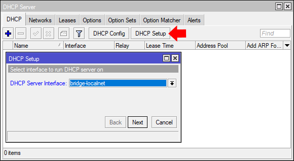
Для автоматической раздачи устройствам в сети IP адресов и необходимых сетевых настроек настраиваем DHCP сервер. Переходим IP -> DHCP Server , в открывшемся окне на вкладке DHCP нажимаем DHCP Setup . Откроется мастер настройки, на первой вкладке в поле DHCP Server Interface выбираем созданный ранее Bridge интерфейс. Нажимаем Next .
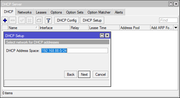
DHCP Address Space - указываем адресное пространство, в котором будет производиться выдача IP адресов, указывается как Network/Mask . Для тех, кто не понимает, что здесь надо вводить, то Network можно подсмотреть в разделе IP -> Addresses , а Mask взять из префикса в поле Address там же. Нажимаем Next .
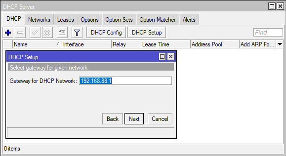
Gateway For DHCP Network - адрес маршрутизатора в сети. Т.к. мы настраиваем устройство как маршрутизатор для доступа наших устройств к сети интернет, то указываем ранее присвоенный адрес устройству, маску сети в данном пункте указывать не надо. Нажимаем Next .
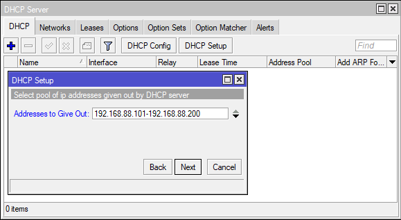
Addresses to Give Out - диапазон IP адресов, из которого DHCP сервер будет выдавать адреса подключенным устройствам в сети. Для сети /24 можно выдать 254 адреса, не забываем, что один адрес уже используется маршрутизатором и его необходимо исключить из этого диапазона. Нажимаем Next .
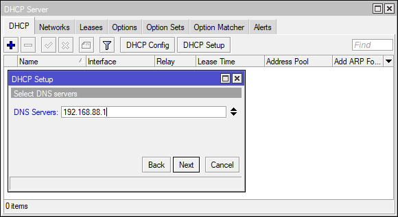
DNS Servers - адрес или несколько адресов где расположен(ы) сервис(ы) преобразования доменных имен в IP адреса. В домашних сетях указываем адрес настраиваемого нами маршрутизатора. Нажимаем Next .
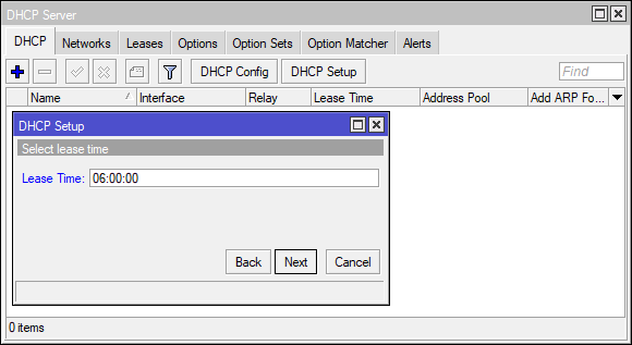
Lease Time - Время резервирования IP адреса за устройством в сети. После истечения данного времени если устройство продолжает работать, то время аренды обновляется и IP адрес остается за данным устройством, если устройство нет в сети, то IP адрес может быть зарезервирован за другим устройством. Нажимаем Next .
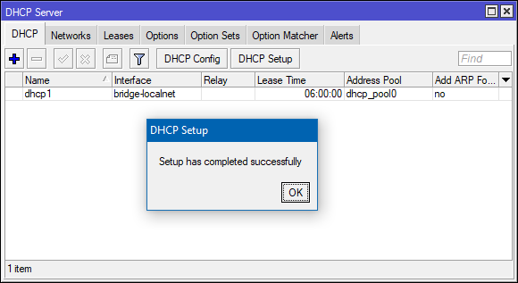
На этом работа мастера завершается, DHCP настроен.
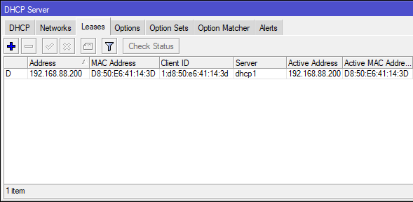
На вкладке Leases проверяем что компьютер, с которого производится настройка MikroTik получил IP адрес.
Переподключаемся к настраиваемому устройству ( Session -> Disconnect ) для проверки работы локальной сети.
Минимальная настройка Firewall
Для предотвращения несанкционированного доступа к маршрутизатору и устройствам в локальной сети из сети интернет добавляем необходимые правила в Firewall.
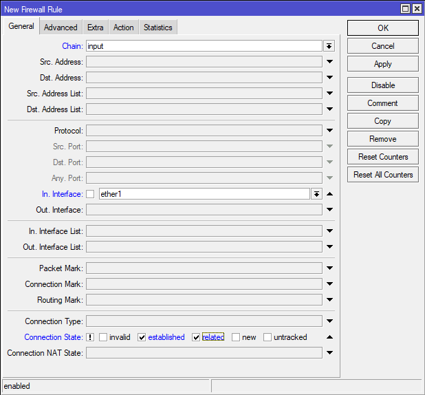
Переходим в раздел IP -> Firewall , на вкладке Filter Rules нажимаем + . В открывшемся окне на вкладке General добавляем:
- Chain - Input
- In. Interface - ether1
- Connection State - отмечаем в окне первый не подписанный квадрат, он выделится восклицательным знаком, далее выбираем established и related
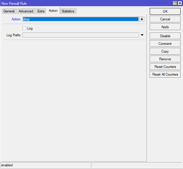
Переходим на вкладку Action , в поле Action выбираем drop . Нажимаем OK .
Немного пояснений к описанному выше. В поле In. Interface мы указали интерфейс ether1 , именно к этому порту у нас будет подключен в скором будущем провод провайдера, если вы планируете использовать для подключения к интернет другой порт, то необходимо указать его. Интерфейс, предназначенный для подключения к сети интернет не должен входить в созданный ранее Bridge интерфейс!
Созданное правило будет блокировать все входящие пакеты, адресованные настраиваемому маршрутизатору из внешней сети (в данном случае приходящие на интерфейс ether1 ), кроме уже установленных подключений, инициированных маршрутизатором.
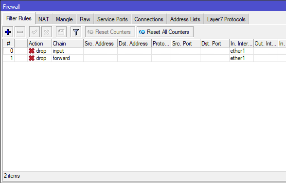
На основе текущего правила создадим еще одно, оно будет похоже на первое, только будет действовать на проходящие пакеты через маршрутизатор из внешней сети к устройствам в локальной сети. Открываем созданное правило и жмем кнопку Copy , в новом окне в поле Chain выбираем forward . В обоих окнах нажимаем OK .
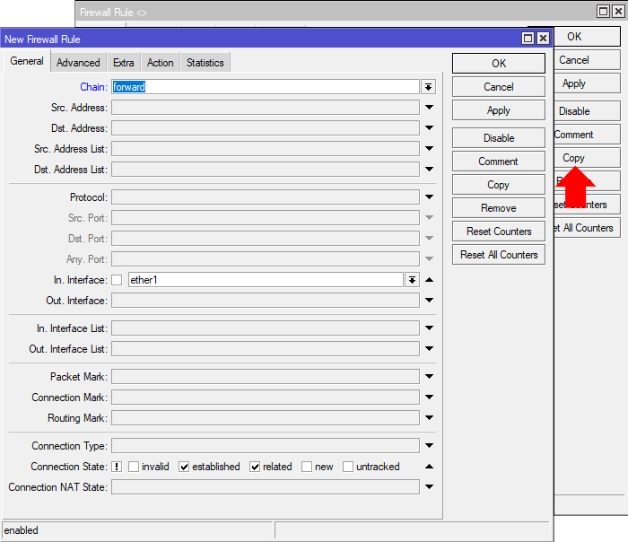
В итоге у нас в списке Filter Rules должно появиться два запрещающих правила.
Для доступа устройств локальной сети в сеть интернет настраиваем NAT на соответствующей вкладке нажав + . В окне создания правила на вкладке General заполняем:
- Chain - srcnat
- Out. Interface - ether1
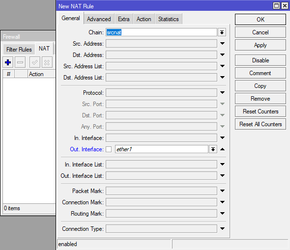
Переходим на вкладку Action , в поле Action выбираем masquerade . Нажимаем OK .
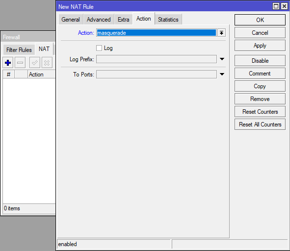
Созданное правило будет подменять на исходящих пакетах во внешнюю сеть IP адрес устройства локальной сети на IP адрес маршрутизатора назначенному интерфейсу, к которому подключен провод провайдера.
Это минимальный набор правил для защиты устройств в сети, для более глубокого погружения в тему настройки Firewall рекомендую к прочтению статью: Настройка Firewall на шлюзе MikroTik.
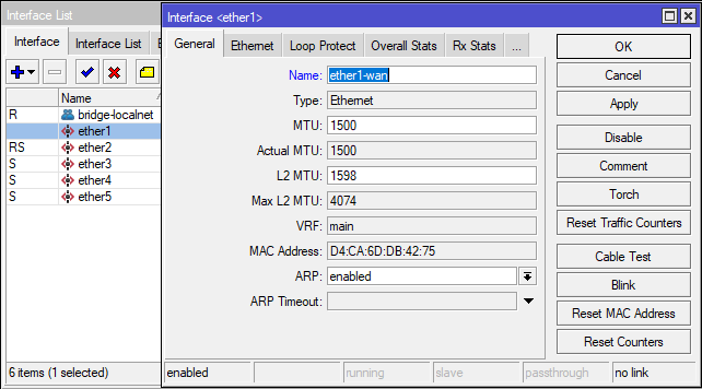
Настройка интернет
Как я говорил ранее, провод интернет провайдера будем подключать в первый порт на устройстве, это ни с чем не связано, просто для удобства. В меню Interfaces двойным нажатием открываем свойства ether1 и поле Name записываем ether1-wan . Сохраняем кнопкой OK . Это сделано для удобства чтения конфигурации, если зайти в раздел Firewall, то увидим, что в созданных ранее правилах In. Interface поменялся на ether1-wan . В дальнейшем по тексту он будет называться коротко - WAN .
Некоторые интернет провайдеры привязывают MAC адрес клиентского устройства к выдаваемым IP адресам или для ограничения доступа, поэтому если у вас сменилось оборудование не забываем позвонить провайдеру и сообщить MAC address WAN интерфейса.
Если общение со службой поддержки провайдера у вас вызывает какие-то проблемы, то MAC адрес можно сменить на WAN интерфейсе самому. Изменение MAC адреса выполняется только из командной строки, нажимаем New Terminal в открывшемся окне вводим:
/interface/ethernet/set ether1-wan mac-address=XX:XX:XX:XX:XX:XX
где XX:XX:XX:XX:XX:XX новый MAC адрес интерфейса.
Теперь необходимо назначить IP адрес WAN интерфейсу, это делается одним из двух способов, какой из них необходим вам надо уточнить в тексте договора либо в техподдержке провайдера.
- Получение IP адреса от оборудования провайдера по DHCP автоматически.
- Прописывание IP адреса вручную.
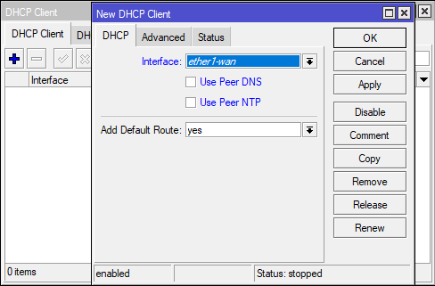
Получение IP адреса по DHCP (Вариант #1). Переходим IP -> DHCP Client , на вкладке DHCP Client нажимаем + . В окне New DHCP Client заполняем:
- Interface - выбираем WAN интерфейс.
- Use Peer DNS - использование серверов DNS провайдера. Если будут использоваться другие, например, DNS сервера Google, то снимаем галочку.
- Use Peer NTP - использование серверов провайдера для синхронизации времени. Если будут использоваться другие, например, NTP сервера Google, то снимаем галочку.
- Add Default Route - автоматическое добавление и использование по умолчанию шлюза провайдера в таблице маршрутизации.
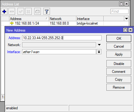
Прописывание IP адреса вручную (Вариант #2). Переходим IP -> Addresses , в окне Address List нажимаем + , откроется окно добавления IP адреса интерфейсу, указываем:
- Address - IP адрес маршрутизатора в сети провайдера и маска сети. Мы уже раньше рассматривали что маска сети записывается как префикс, но в договорах провайдер обычно пишет маску полностью, поэтому через прямой слеш записываем как указано в договоре, например, 10.22.33.44/255.255.252.0 , при сохранении префикс будет автоматически рассчитан из записи маски.
- Interface - выбираем созданный нами WAN интерфейс (ether1-wan).
Поле Network оставляем неактивным, оно заполнится автоматически на основе внесенной маски сети, нажимаем OK .
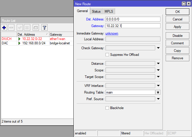
Добавляем маршрут по умолчанию. Если маршрутизатор получает IP адрес от DHCP сервера и выставлена настройка Add Default Gateway = yes , то настраивать ничего не надо! Переходим IP -> Route , в окне Route List нажимаем + . Заполняем следующие поля:
- Dst. Address - адрес назначения, для маршрута по умолчанию устанавливается 0.0.0.0/0 .
- Gateway - шлюз для маршрута. IP адрес, маска сети и шлюз обычно прописаны в договоре провайдера.
Настройка DNS сервера
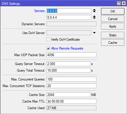
Для корректного доступа к сети интернет маршрутизатора и устройств локальной сети осталось настроить DNS сервер. Переходим IP -> DNS , в поле Servers вносим IP адреса DNS серверов Google (8.8.8.8 и 8.8.4.4). Включаем настройку Allow Remote Requests, теперь маршрутизатор будет выступать в качестве DNS сервера для устройств в локальной сети. Нажимаем OK .
Заключение
Теперь мы можем подключить провод провайдера в WAN порт на MikroTik.
Если все настройки сделаны верно, то на маршрутизаторе и на компьютере, с которого выполнялась настройка должен появиться интернет. Для проверки на MikroTik запускаем New Terminal , в консоли вводим:
ping 8.8.8.8
До завершения полной настройки устройства осталось рассмотреть настройку Wi-Fi, настройку синхронизации времени в сети и некоторые настройки для повышения безопасности устройства, все это описано во второй части статьи: Настройка маршрутизатора MikroTik с нуля (RouterOS 7). [Часть 2]
Manual:IP/Route
Router keeps routing information in several separate spaces:
- FIB (Forwarding Information Base), that is used to make packet forwarding decisions. It contains a copy of the necessary routing information.
- Each routing protocol (except BGP) has it's own internal tables. This is where per-protocol routing decisions are made. BGP does not have internal routing tables and stores complete routing information from all peers in the RIB.
- RIB contains routes grouped in separate routing tables based on their value of routing-mark. All routes without routing-mark are kept in the main routing table. These tables are used for best route selection. The main table is also used for nexthop lookup.
Routing Information Base
RIB (Routing Information Base) contains complete routing information, including static routes and policy routing rules configured by the user, routing information learned from routing protocols, information about connected networks. RIB is used to filter routing information, calculate best route for each destination prefix, build and update Forwarding Information Base and to distribute routes between different routing protocols.
By default forwarding decision is based only on the value of destination address. Each route has dst-address property, that specifies all destination addresses this route can be used for. If there are several routes that apply to a particular IP address, the most specific one (with largest netmask) is used. This operation (finding the most specific route that matches given address) is called routing table lookup.
If routing table contains several routes with the same dst-address, only one of them can be used to forward packets. This route is installed into FIB and marked as active.
When forwarding decision uses additional information, such as a source address of the packet, it is called policy routing. Policy routing is implemented as a list of policy routing rules, that select different routing table based on destination address, source address, source interface, and routing mark (can be changed by firewall mangle rules) of the packet.
All routes by default are kept in the main routing table. Routes can be assigned to specific routing table by setting their routing-mark property to the name of another routing table. Routing tables are referenced by their name, and are created automatically when they are referenced in the configuration.
Each routing table can have only one active route for each value of dst-address IP prefix.
There are different groups of routes, based on their origin and properties.
Default route
Route with dst-address 0.0.0.0/0 applies to every destination address. Such route is called the default route. If routing table contains an active default route, then routing table lookup in this table will never fail.
Connected routes

Connected routes are created automatically for each IP network that has at least one enabled interface attached to it (as specifie in the /ip address configuration). RIB tracks status of connected routes, but does not modify them. For each connected route there is one ip address item such that:
- address part of dst-address of connected route is equal to network of ip address item.
- netmask part of dst-address of connected route is equal to netmask part of address of ip address item.
- pref-src of connected route is equal to address part of address of ip address item.
- interface of connected route is equal to actual-interface of ip address item (same as interface, except for bridge interface ports).
Multipath (ECMP) routes
Because results of the forwarding decision are cached, packets with the same source address, destination address, source interface, routing mark and ToS are sent to the same gateway. This means that ECMP route does not perform pure per-connection balancing, but it can be used to load balance connections if at least one of previously mentioned parameters is different than previous connection. See interface bonding if you need to achieve per-packet load balancing.
To implement some setups, such as load balancing, it might be necessary to use more than one path to given destination. However, it is not possible to have more than one active route to destination in a single routing table.
ECMP (Equal cost multi-path) routes have multiple gateway nexthop values. All reachable nexthops are copied to FIB and used in forwarding packets.
OSPF protocol can create ECMP routes. Such routes can also be created manually.
Routes with interface as a gateway
Value of gateway can be specified as an interface name instead of the nexthop IP address. Such route has following special properties:
- Unlike connected routes, routes with interface nexthops are not used for nexthop lookup.
- It is possible to assign several interfaces as a value of gateway, and create ECMP route. It is not possible to have connected route with multiple gateway values.
Route selection
Each routing table can have one active route for each destination prefix. This route is installed into FIB. Active route is selected from all candidate routes with the same dst-address and routing-mark, that meet the criteria for becoming an active route. There can be multiple such routes from different routing protocols and from static configuration. Candidate route with the lowest distance becomes an active route. If there is more than one candidate route with the same distance, selection of active route is arbitrary (except for BGP routes).
BGP has the most complicated selection process (described in separate article). Notice that this protocol-internal selection is done only after BGP routes are installed in the main routing table; this means there can be one candidate route from each BGP peer. Also note that BGP routes from different BGP instances are compared by their distance, just like other routes.
Criteria for selecting candidate routes
To participate in route selection process, route has to meet following criteria:
- route is not disabled.
- distance is not 255. Routes that are rejected by route filter have distance value of 255.
- pref-src is either not set or is a valid local address of the router.
- routing-mark is either not set or is referred by firewall or policy routing rules.
- If type of route is unicast and it is not a connected route, it must have at least one reachable nexthop.
Nexthop lookup

Nexthop lookup is a part of the route selection process.
Routes that are installed in the FIB need to have interface associated with each gateway address. Gateway address (nexthop) has to be directly reachable via this interface. Interface that should be used to send out packets to each gateway address is found by doing nexthop lookup.
Some routes (e.g. iBGP) may have gateway address that is several hops away from this router. To install such routes in the FIB, it is necessary to find the address of the directly reachable gateway (an immediate nexthop), that should be used to reach the gateway address of this route. Immediate nextop addresses are also found by doing nexthop lookup.
Nexthop lookup is done only in the main routing table, even for routes with different value of routing-mark. It is necessary to restrict set of routes that can be used to look up immediate nexthops. Nexthop values of RIP or OSPF routes, for example, are supposed to be directly reachable and should be looked up only using connected routes. This is achieved using scope and target-scope properties.
- Routes with interface name as the value of gateway are not used for nexthop lookup. If route has both interface nexthops and active IP address nexthops, then interface nexthops are ignored.
- Routes with scope greater than the maximum accepted value are not used for nexthop lookup. Each route specifies maximum accepted scope value for it's nexthops in the target-scope property. Default value of this property allows nexthop lookup only through connected routes, with the exception of iBGP routes that have larger default value and can lookup nexthop also through IGP and static routes.

Recursive nexthop lookup example
- nexthop 10.2.0.1 is resolved through a connected route, it's status is reachable.
- nexthop 10.3.0.1 is resolved recursively through a 10.3.0.0/16 route, it's status is recursive, and it uses 10.2.0.1 as the immediate nexthop value that is installed in the FIB.
Interface and immediate nexthop are selected based on the result of nexthop lookup:
- If most specific active route that nexthop lookup finds is connected route, then interface of this connected route is used as the nexthop interface, and this gateway is marked as reachable. Since gateway is directly reachable through this interface (that's exactly what connected route means), the gateway address is used as the immediate nexthop address.
- If most specific active route that nexthop lookup finds has nexthop that is already resolved, immediate nexthop address and interface is copied from that nexthop and this gateway is marked as recursive.
- If most specific active route that nexthop lookup finds is ECMP route, then it uses first gateway of that route that is not unreachable.
- If nexthop lookup does not find any route, then this gateway is marked as unreachable.
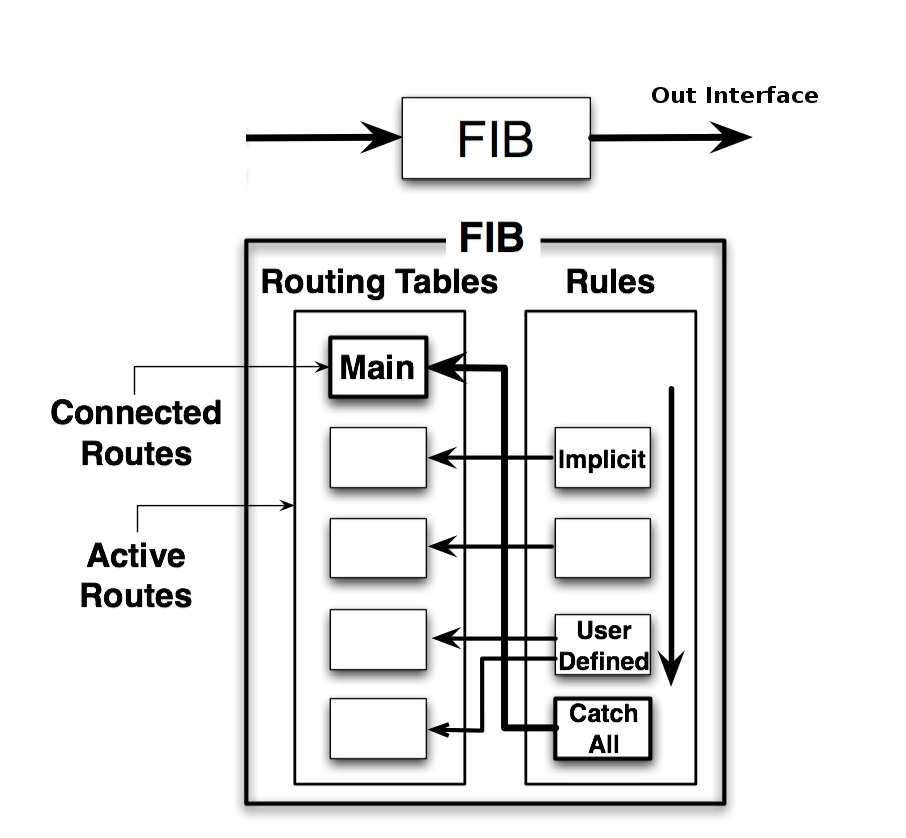
Forwarding Information Base

FIB (Forwarding Information Base) contains copy of information that is necessary for packet forwarding:
- all active routes
- policy routing rules
By default (when no routing-mark values are used) all active routes are in the main table, and there is only one hidden implicit rule ("catch all" rule) that uses the main table for all destination lookups.
Routing table lookup
FIB uses following information from packet to determine it's destination:
- source address
- destination address
- source interface
- routing mark
- ToS (not used by RouterOS in policy routing rules, but it is a part of routing cache lookup key)
Possible routing decisions are:
- receive packet locally
- discard packet (either silently or by sending ICMP message to the sender of the packet)
- send packet to specific IP address on specific interface
Results of routing decision are remembered in the routing cache. This is done to improve forwarding performance. When another packet with the same source address, destination address, source interface, routing mark and ToS is routed, cached results are used. This also allows to implement load balancing using ECMP routes, because values used to lookup entry in the routing cache are the same for all packets that belong to the same connection and go in the same direction.
If there is no routing cache entry for this packet, it is created by running routing decision:
- check that packet has to be locally delivered (destination address is address of the router)
- process implicit policy routing rules
- process policy routing rules added by user
- process implicit catch-all rule that looks up destination in the main routing table
- return result is "network unreachable"
Result of routing decision can be:
- IP address of nexthop + interface
- point-to-point interface
- local delivery
- discard
- ICMP prohibited
- ICMP host unreachable
- ICMP network unreachable
Rules that do not match current packet are ignored. If rule has action drop or unreachable, then it is returned as a result of the routing decision process. If action is lookup then destination address of the packet is looked up in routing table that is specified in the rule. If lookup fails (there is no route that matches destination address of packet), then FIB proceeds to the next rule. Otherwise:
- if type of the route is blackhole, prohibit or unreachable, then return this action as the routing decision result;
- if this is a connected route, or route with an interface as the gateway value, then return this interface and the destination address of the packet as the routing decision result;
- if this route has IP address as the value of gateway, then return this address and associated interface as the routing decision result;
- if this route has multiple values of nexthop, then pick one of them in round robin fashion.
Result of this routing decision is stored in new routing cache entry.
Properties
Route flags
Property(Flag) Description disabled (X) Configuration item is disabled. It does not have any effect on other routes and is not used by forwarding or routing protocols in any way. active (A) Route is used for packet forwarding. See route selection. dynamic (D) Configuration item created by software, not by management interface. It is not exported, and cannot be directly modified. connect (C) connected route. static (S) static route. rip (r) RIP route. bgp (b) BGP route. ospf (o) OSPF route. mme (m) MME route. blackhole (B) Silently discard packet forwarded by this route. unreachable (U) Discard packet forwarded by this route. Notify sender with ICMP host unreachable (type 3 code 1) message. prohibit (P) Discard packet forwarded by this route. Notify sender with ICMP communication administratively prohibited (type 3 code 13) message. General properties
- connected routes: 0
- static routes: 1
- eBGP: 20
- OSPF: 110
- RIP: 120
- MME: 130
- iBGP: 200
- connected routes: 10 (if interface is running)
- OSPF, RIP, MME routes: 20
- static routes: 30
- BGP routes: 40
- connected routes: 200 (if interface is not running)
Other Read-only properties
Property Description gateway-status (array) Array of gateways, gateway states and which interface is used for forwarding. Syntax "IP state interface", for example "10.5.101.1 reachable bypass-bridge". State can be unreachable, reachable or recursive. See nexthop lookup for details. ospf-metric (integer) Used OSPF metric for particular route ospf-type (string) BGP Route Properties
These properties contain information that is used by BGP routing protocol. However, values of these properties can be set for any type of route, including static and connected. It can be done either manually (for static routes) or using route filters.
- internet - advertise this route to the Internet community (i.e. all routers)
- no-advertise - do not advertise this route to any peers
- no-export - do not advertise this route to EBGP peers
- local-as - same as no-export, except that route is also advertised to EBGP peers inside local confederation
Property Description bgp-ext-communities (string) Value of BGP extended communities attribute bgp-weight (integer) Additional value used by BGP best path selection algorithm. Routes with higher weight are preferred. It can be set by incoming routing filters and is useful only for BGP routes. If value is not set then it is interpreted as 0. received-from (string) Name of the BGP peer from which route is received.