What is the difference between different types of GND
I would like to know the difference between different types of Grounds like AGND, SGND, Battery Gnd, PGND. Are all the grounds not same? Cant we connect the device to any one of these grounds?
asked Nov 26, 2014 at 6:37
203 1 1 gold badge 2 2 silver badges 8 8 bronze badges
\$\begingroup\$ I can not anderstand why this question it is apvoted, since this question is answered many times, with much more details than you get bellow. -1 because you did not dig. There is nice search function in the upper right corner. \$\endgroup\$
Nov 26, 2014 at 17:16
\$\begingroup\$ @GRTech The standard method for expressing this is by flagging it as a duplicate and tagging the questions that you think address it already — this allows it to be managed correctly — either the question is a duplicate, or it just sounds like one. Flagging it allows the debate. Additionally, the links help others to find the appropriate question. Many users arrive here from Google — a link to a better-answered question would be more helpful than this grumbling. It’s a lot more friendly to newcomers also who maybe don’t know the rules/conventions for stackexchange. \$\endgroup\$
Jan 18 at 11:45
3 Answers 3
\$\begingroup\$
Though they all all contain «GND» they are not really mean the earth, we only have one earth, but can have many «GND»s. You can think GND as a common reference point of a local system.
From your «GND»s, the AGND, may represent the «analog ground», SGND may represent «signal ground», PGND may represent «power ground». For some reasons, such as safety, EMI, etc., we tend to split our system into many sub-systems. Every ground just is a reference point of the sub-systems.
If your device doesn’t belong to a system, you can’t connect your device to the ground of that system.
answered Nov 26, 2014 at 7:27
5,838 5 5 gold badges 44 44 silver badges 82 82 bronze badges
\$\begingroup\$ It is more consistent to think of ‘ground’ as ‘return path’, this will make it easier when you have to consider EMC issues as well. So each ‘ground’ is actually a different sort of ‘return path’ for a signal. For example, a safety ‘earth’ is a good return path for current which shouldn’t escape the enclosure, but isn’t usually a good path for high frequency signals. Thinking of ‘ground’ as a uniform 0V potential will cause confusion once you get past the most basic of circuits. \$\endgroup\$
Nov 26, 2014 at 16:21
\$\begingroup\$ I think the OP may concern the GND «point», actually, there always some voltage drop on a «path», so only one point is the really GND point, that is the common reference point, even the points on your «path» should reference to this point. \$\endgroup\$
Nov 26, 2014 at 16:26
\$\begingroup\$
Ideally all grounds are the same. However, there may be reasons they aren’t the same:
- Your ground has significant DC current flowing through it. From Ohm’s law, we know \$V = IR\$, so there will be a slight voltage gradient across your «ground».
- Similarly, for high frequencies, ground has some non-zero inductance. An inductor at high frequency has significant impedance, leading to a potential difference at these high frequencies.
- Ground is a label for a reference point. Sometimes you don’t want your reference point to be physically tied to the literal ground, or want isolated reference points (known as «galvanic isolation»).
Usually high frequencies are on the digital side, where you are switching at a high rate (worse, these are square waves so there are higher harmonics). Analog circuits usually imply you care about the amplitude/other features of the waveform, and these high frequencies from digital circuits can easily corrupt your signal. Thus it’s not uncommon to have a divider between analog and digital grounds. However, crucially both grounds are still tied together (preferably at a single point) so you have the same reference point. There are other things to consider here, but I’m omitting them for brevity.
For circuits with significant DC current and sensitive analog components, it’s not uncommon to divide the power ground from your analog ground. Again, you would tie these together at a single point to have a common reference.
Galvanic isolation is used for various reasons. One of the big reasons is safety. For example, most power bricks are isolated supplies. If there is a failure on the primary side, as long as you don’t exceed the isolation voltage limit your second side usually just loses power instead of being shorted to the primary side plugged into the wall. In this case, you physically have two separate reference points. Their potentials can float such that the voltage across the two grounds is not zero. Sometimes there is some effort made that this potential doesn’t drift too far away.
What is Agnd and Pgnd?
PGND is the ground connection over which higher pulsed currents flow. AGND, sometimes called SGND (signal ground), is the ground connection that the other, usually very calm, signals use as a reference. This includes the internal voltage reference needed for the regulation of the output voltage.
What is analog ground and digital ground?
The labels, “analog ground” and “digital ground,” on these pins refer to the internal parts of the converter to which the pins are connected and not to the system grounds to which they must go. For an ADC, these two pins should generally be joined together and to the analog ground of the system.
What is power ground and signal ground?
Power Ground is the low side (0V) of the power input. The GND on the schematic is connected. directly to PIN 1 and PIN 4 of the BLACK power input connector and is thus. connected to the low side of the customers power supply. Signal Ground is applicable to those ED/ES products which have a serial gateway or serial port …
What does GND mean in electronics?
Ground
What Does Ground (GND) Mean? Ground, in the context of electronics, is the reference point for all signals or a common path in an electrical circuit where all of the voltages can be measured from. This is also called the common drain since the voltage measurement along it is zero.
What does Agnd stand for?
| Acronym | Definition |
|---|---|
| AGND | Audio Ground |
| AGND | Analog Ground |
What is logic ground?
Digital logic ground is the “reference” terminal of a power supply for your digital logic. For most digital logic systems, it’s the negative terminal of the logic power supply, usually shown with the symbol in Figure 1 . Analog ground is the reference terminal of the supply that powers an analog circuit.
What is difference between ground and digital ground?
digital ground analog ground The diference is the noise. The digital gnd is much more noiser that analog agnd, so they should not be mix up to avoid coupling from digital noise to analog. Use decoupling capacitors (for IC…etc) and in real life you can use analog ground for digital ground at the same time.
What is the difference between analog and digital grounding?
Digital Ground usually refers to the reference voltage of digital logic ICs. This means that no analog signals are coupled into this reference plane. You can often see analog and digital ground where digital ground will be the reference for any logic and analog ground will be the return path for any analog circuits.
Is zero volt a ground?
Source: Wikipedia. But ground as zero voltage is theoretical; only a conductor with zero impedance will have zero voltage. In reality, a ground plane or rail will usually have varying voltages at negligible levels.
Is common and ground the same?
Common ground, or simply common, isn’t a physical ground; rather, it’s just a reference point in a circuit for voltage measurements. That way, the circuit is said to have both positive and negative power supplies.
What is the difference between 0v and ground?
Zero volts or Vgnd is just a reference point from which all circuit measurements are taken. It is usually denoted by the ground symbol. “Ground exists only in the mind of the person analyzing the circuit” . It is useful to remember that voltage is defined as potential DIFFERENCE.
What’s the difference between a GND and a PGND?
What happens when AGND and PGND are separated?
What does PGND mean in a switching regulator?
Why do they seperate PGND and GND in PCB?
Difference between GND and PGND
HI, I m using a SLIC Ag1460. There are two grounds associated with it. A simple GND and a PGND (Power Ground). I want to know that are GND and PGND same or different from each other. What should i do to to connect a pin to PGND.
Timely answer to this is the key for success to my project.
maziaar83
Junior Member level 2
Joined Jan 31, 2007 Messages 23 Helped 0 Reputation 0 Reaction score 0 Trophy points 1,281 Activity points 1,412
what is pgnd
Hey man!
they are completely different!
do not connect them together! never!
DrWhoF
Advanced Member level 1
Joined May 6, 2005 Messages 402 Helped 24 Reputation 48 Reaction score 11 Trophy points 1,298 Activity points 4,388
I think they have to be connected at one point.
Take a look in this PDF file at PCB layout and circuit diagram:
**broken link removed**
xerxer
Junior Member level 3
Joined Nov 15, 2005 Messages 29 Helped 0 Reputation 0 Reaction score 0 Trophy points 1,281 Activity points 1,523
i think this relate to kelvi connetion. so you can not connect the two pad in dircect
kevpat
Member level 2
Joined Nov 26, 2006 Messages 47 Helped 7 Reputation 14 Reaction score 0 Trophy points 1,286 Location Scotland Activity points 1,612
Kashi, You will need to connect the grounds at a star-point usually as close as possible to the power input/output point on your pcb. This should be the only point they connect to stop large pwr GND circulating currents effecting sensitive circuitry connected to your GND plane.
wichayen
Member level 2
Joined Jan 31, 2007 Messages 46 Helped 2 Reputation 4 Reaction score 0 Trophy points 1,286 Location Thailand Activity points 1,576
As datasheet that posted by DrWhoF.
PGND and GND is the same reference level. So you I think you should connect it together (by star connection).
The reason why they seperate PGND and GND is to avoid noise interference from GND to PGND. usually power circuit is low frequency and digital circuit is high frequency. You can see in datasheet that posted by DrWhoF. The inner layer2,3 of PCB seperate 2 area. because they want to connect PGND and GND only one point (star connection).
kender
Advanced Member level 4
Joined Jun 19, 2005 Messages 1,425 Helped 138 Reputation 276 Reaction score 39 Trophy points 1,328 Location Stanford, SF Bay Peninsula, California, Earth, Sol Activity points 10,035
difference -vss and gnd
You should connect GND and PGND at exactly one point on your board (or, may be, one point in your whole instrument). This is called «star ground», or «totem pole ground». You can find a simple diagram of the star ground here
What is GND in a Circuit?

In this article, you will learn the classification of GND and its working principle. GND is an abbreviation for the ground. GND represents the ground wire or the 0 wire. This ground is not a real ground, it is a ground assumed for the purpose of application. For the power supply, it is the negative pole of a power supply.

Catalog
What is GND in a circuit? During the PCB Layout routing process, engineers are faced with different GND handling. Why? In the circuit principle design stage, in order to reduce mutual interference between circuits, engineers generally introduce different GND grounds as 0V reference points for different functional circuits, forming different current loops.
Classification of GND
1 Analog ground AGND
Analog ground AGND is mainly used in the analog circuit part, such as the ADC acquisition circuit of analog sensors, operation amplification proportional circuit, etc.
In these analog circuits, because the signal is analog and weak, it is easily affected by high currents from other circuits. If not distinguished, the large current will produce a large voltage drop in the analog circuit, which will make the analog signal distorted and may seriously cause the analog circuit function to fail.
2 Digital ground DGND
Digital ground DGND, obviously relative to analog ground AGND, is mainly used in digital circuits, such as key detection circuits, USB communication circuits, microcontroller circuits, etc.
The reason why digital ground DGND is set up is that digital circuits have a common feature. They are all discrete open light signals, only the number «0» and the number «1» to distinguish, as shown in the figure below.
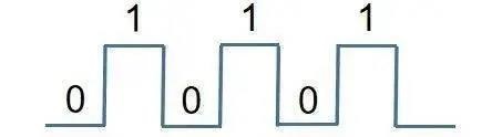
During the transition from the digital «0» voltage to the digital «1» voltage, or the transition from the digital «1» voltage to the digital «0» voltage, the voltage has a change. According to Maxwell’s electromagnetic theory, the change A magnetic field is generated around the current, which forms EMC radiation to other circuits.
In order to reduce the EMC radiation impact of the circuit, a separate digital ground DGND must be used so that other circuits are effectively isolated.
3 Power ground PGND
Analog ground AGND or digital ground DGND, are all low power circuits. In high-power circuits, such as motor drive circuits, solenoid valve drive circuits, etc., there is also a separate reference ground, which is called the power ground PGND.
High-power circuits, as the name implies, are relatively large current circuits. Obviously, large currents are likely to cause ground offsets between circuits with different functions, as shown in the figure below.

Once there is a ground shift in the circuit, the original 5V voltage may not be 5V, but 4V. Because the 5V voltage is referred to the GND ground line 0V, if the ground offset causes the GND line to rise from 0V to 1V, then the previous 5V (5V-0V=5V) voltage becomes the current 4V (5V-1V= 4V) again.
4 Power supply GND
Analog ground AGND, and digital ground DGND, and power ground PGND, are all classified as DC ground GND. These different types of ground, finally all come together as a 0V reference ground for the whole circuit, this ground is called power ground GND.
The voltage and current required for all circuits to work come from the power supply. Therefore, the GND of the power supply is the 0V voltage reference point for all circuits.
This is why other types of ground, whether it is analog ground AGND, digital ground DGND, or power ground PGND, all need to be brought together with the power supply ground GND at the end.
5 AC ground CGND
AC ground CGND is generally present in circuit projects containing AC power, such as AC to DC power circuits.
AC-DC power supply circuit is divided into two parts. The front stage of the circuit is the AC part and the backstage of the circuit is the DC part, which forces the formation of two grounds, one for the AC ground and the other for the DC ground.
The AC ground serves as the 0V reference point for the AC portion of the circuit, and the DC ground serves as the 0V reference point for the DC portion of the circuit. Usually, in order to unify a ground GND in a circuit, engineers connect the AC ground to the DC ground through a coupling capacitor or inductor.
6 Earth ground EGND
The safe voltage for the human body is below 36V. Voltages exceeding 36V can cause damage to the human body if applied to the body, which is a common sense safety for engineers in developing and designing circuit project solutions.
In order to enhance the safety factor of the circuit, engineers generally use the earth ground EGND in high-voltage and high-current projects, such as in the circuits of household appliances electric fans, refrigerators, and televisions. The socket with earth ground EGND protection is shown in the picture below.
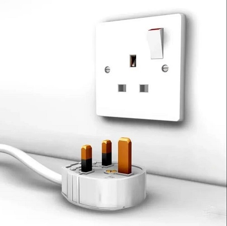
220V AC only needs the fire wire and zero wire. Why socket for household appliances have 3 terminals?
The two of 3 terminals of the socket are used for the 220V fire and zero wires, and the other terminal-the earth ground EGND is to play a protective role.
The earth ground EGND, it is only connected to our earth, to play a high-voltage protection role. It is not involved in the project circuit function.
Therefore, the meaning of EGND and other types of GND circuits are significantly different.
Working principle of GND
How can a ground GND have so many distinctions, and how can a simple circuit problem be made so complicated?
Why is it necessary to introduce so many subdivision of the GND ground function?
Generally, engineers simply named this type of GND ground wire design as GND. There is no distinction in the schematic design process, which makes it difficult to effectively identify the GND ground wires of different circuit functions during PCB layout. They directly and simply connect all GND ground wires together.
Although this is easy to operate, it will lead to a series of problems.
1 Signal crosstalk
If the different functions of the ground GND are directly connected together, high-power circuits through the ground GND, will affect the 0V reference point GND of low-power circuits so that the crosstalk between the signals of different circuits is generated.
2 Signal accuracy
The core indicator of the Analog circuit is the accuracy of the signal. Without accuracy, the analog circuit loses its original functional significance.
The ground CGND of the AC power supply is a sine wave that fluctuates up and down periodically. Its voltage also fluctuates up and down, not always maintained at a constant 0V like the DC ground GND.
Connecting the ground GND of different circuits together, the cyclically changing AC ground CGND will drive the analog circuit ground AGND to change, which will affect the voltage accuracy value of the analog signal.
3 EMC experiment
The weaker the signal is, the weaker the EMC of external electromagnetic radiation is. The stronger the signal is, the stronger the EMC of external electromagnetic radiation is.
If the GND of different circuits are connected together, the GND of the circuit with strong signal directly interferes with the GND of the circuit with weak signal. The consequence is that the EMC with a weak signal becomes the source of strong external EMR, which increases the difficulty of the circuit processing EMC experiment.
4 Circuit reliability
Between circuit systems, the fewer the parts of the signal connection, the stronger the ability of the circuit to operate independently; the more the parts of the signal connection, the weaker the ability of the circuit to operate independently.
If there is no intersection between two circuit systems A and B, it is obvious that the function of circuit system A cannot affect the normal operation of circuit system B. Similarly, the function of circuit system B cannot affect the normal operation of circuit system A.
If the circuit ground wires of different functions are connected together in the circuit system, it is equivalent to increasing a link of interference between the circuits, that is, reducing the reliability of circuit operation.


We are the professional distributor of electronic components, providing a large variety of products to save you a lot of time, effort, and cost with our efficient self-customized service. careful order preparation fast delivery service